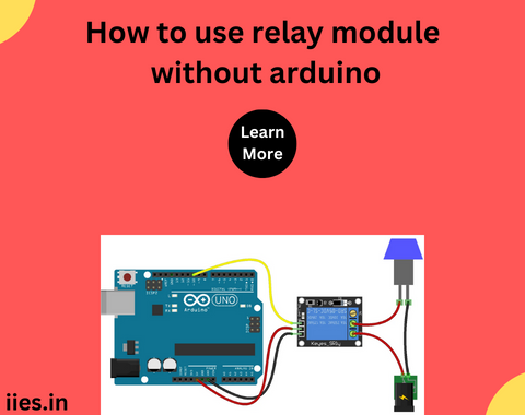
Relay modules are designed to simplify the integration of relays into electronic circuits. They typically come with an optocoupler to isolate the low-voltage control circuit from the high-voltage load, ensuring safety and reliability.
Basic Components
To use a relay module without an Arduino, you’ll need a few basic components:
1. Relay Module: Choose a relay module based on the specifications of your project, considering factors such as the coil voltage, current rating, and the number of channels.
2. Power Supply: Provide a power source for the relay module. Ensure that the voltage matches the specifications of the relay.
3. Switching Device: Use a simple push button or a toggle switch as a manual control mechanism for activating the relay.
4. Load Device: Connect the high-voltage device you want to control, such as a light bulb or a motor.
Wiring Configuration
The wiring configuration for using a relay module without Arduino involves connecting the components in a specific manner. Follow these steps:
1. Connect the Power Supply:
– Connect the positive terminal of the power supply to the VCC or JD-VCC (depending on the relay module).
– Connect the negative terminal of the power supply to the GND terminal on the relay module.
2. Connect the Switching Device:
– Connect one terminal of the switching device (push button or toggle switch) to the IN or Signal terminal on the relay module.
– Connect the other terminal of the switching device to the GND terminal on the relay module.
3. Connect the Load Device:
– Connect one terminal of the high-voltage load device to the Common (COM) terminal on the relay module.
– Connect the other terminal of the load device to the Normally Open (NO) terminal on the relay module.
4. Connect the Relay Coil:
– Connect one terminal of the relay coil to the VCC or JD-VCC terminal.
– Connect the other terminal of the relay coil to the GND terminal.
Operation
Once the wiring is complete, the relay module is ready for operation. When the switching device is activated (pressed or toggled), it sends a signal to the relay module, energizing the relay coil. This, in turn, closes or opens the relay contacts, allowing or interrupting the flow of current to the load device.
Applications
Using relay modules without Arduino opens up various practical applications:
1. Home Automation:
– Control lights, fans, or other appliances with a manual switch.
2. Security Systems:
– Integrate relays into security systems for activating alarms or locking mechanisms.
3. Industrial Automation:
– Incorporate relay modules for basic control functions in industrial settings.
4. DIY Electronics Projects:
– Build custom electronic projects without the need for a microcontroller.
Advanced Configurations and Troubleshooting
While the basic setup described above is sufficient for many applications, there are advanced configurations and troubleshooting tips worth exploring to enhance your understanding of relay modules without Arduino.
Advanced Configurations:
Multiple Relays:
Connect multiple relay modules in parallel for simultaneous control of multiple devices. Ensure that the power supply can provide sufficient current for all the relays.
Feedback Mechanism:
Implement a feedback mechanism by connecting a Normally Closed (NC) relay contact in series with the load. This allows you to detect if the load is actively connected or disconnected.
Time Delay:
Integrate time-delay relays or external timers to introduce delays in activating or deactivating the relay. This can be useful in scenarios where precise timing is required.
Voltage Regulation:
Utilize voltage regulators to ensure a stable power supply for the relay module, especially in situations where fluctuations in the power source may occur.
Troubleshooting Tips:
Check Power Supply:
Ensure that the power supply voltage matches the relay module specifications. A mismatched voltage can lead to unreliable operation.
Verify Wiring Connections:
Double-check all wiring connections to ensure they are secure and correctly configured. Loose connections can result in erratic behavior.
Inspect Switching Device:
If the relay is not responding, inspect the switching device for proper functionality. Clean or replace the switch if necessary.
Diagnose Load Issues:
If the load is not responding, check for issues with the load device itself. Verify that it is operational and within the specified voltage and current ratings.

