What Is a Relay? The Simple Explanation
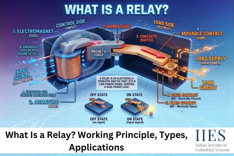
A relay is an electrically operated switch. It uses a small electrical signal to control a much larger one, acting as a bridge between a low-power control circuit and a high-power load circuit.
Think of it this way: you wouldn’t ask a toddler to lift a boulder, but you could ask them to press a button that starts a crane. That’s exactly what a relay does, the small input signal (the toddler) triggers the relay, which then handles the heavy electrical load (the crane).
This ability to use a weak signal to switch a strong one is what makes relays so universally useful in electronics, automotive systems, industrial control, and home appliances.
Relay Working Principle: How Does It Actually Work?
Understanding the relay working principle starts with electromagnetism, specifically, the fact that an electric current passing through a coil of wire creates a magnetic field.
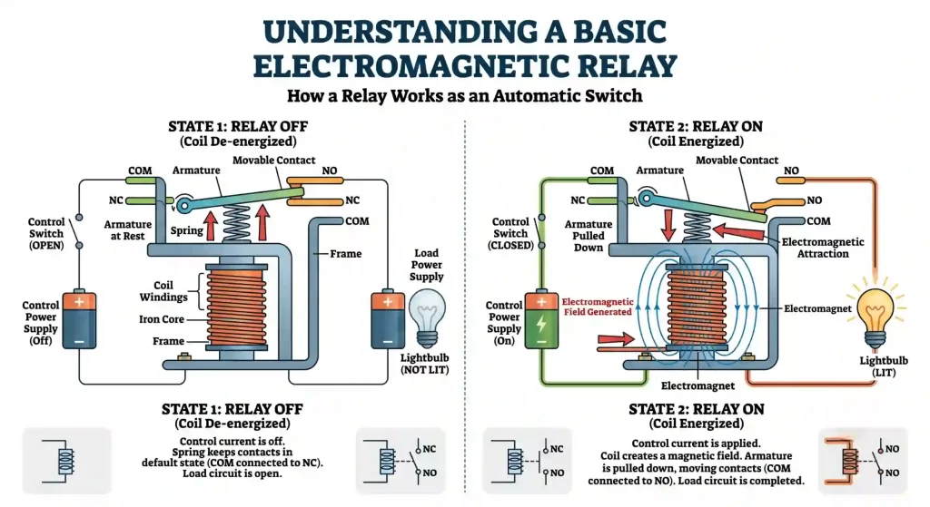
Basic Electromagnetic Relay Working Principle Diagram (Relay ON and OFF States)
Here’s the step-by-step breakdown:
- Control signal arrives — A low-voltage signal (e.g., 5V from a microcontroller) is sent to the relay’s input coil (the electromagnet).
- Electromagnetic field forms — Current through the coil generates a magnetic field.
- Armature moves — The magnetic field attracts a metal armature (a movable lever), pulling it toward the electromagnet.
- Contacts switch — As the armature moves, it physically opens or closes electrical contacts connected to the high-power load circuit.
- Signal removed — Once the control signal stops, the magnetic field collapses, a spring returns the armature to its original position, and the contacts revert.
This elegant mechanical-electrical action is why relays provide true galvanic isolation, the control side and the load side are physically separate, adding a layer of electrical safety that transistors alone can’t match.

Relay Diagram: Understanding the Parts
A standard electromagnetic relay diagram shows these key components:
Component | Function |
Electromagnet (Coil) | Generates magnetic field when energized |
Armature | Movable metal lever pulled by the magnet |
Spring | Returns armature to rest position when de-energized |
Common (COM) | The shared terminal always connected to armature |
Normally Open (NO) | Open when relay is off; closes when energized |
Normally Closed (NC) | Closed when relay is off; opens when energized |
The NO and NC terminals are the heart of the relay’s flexibility. Depending on how you wire your circuit, you can design it to turn something ON or OFF when the relay activates, giving you precise control over complex electrical behavior.
Types of Relay: A Practical Overview
Not all relays are built alike. The type of relay you choose depends on your voltage, current, speed, and environmental requirements.
1. Electromagnetic (Electromechanical) Relay (EMR)
The classic type. Uses a physical coil and mechanical contacts. Durable, reliable, and excellent for high-current switching. The familiar “click” sound comes from these.
Best for: Industrial panels, automotive circuits, HVAC control
2. Solid-State Relay (SSR)
No moving parts. Uses semiconductor devices (transistors, thyristors) to switch the load. Silent, fast, and longer-lasting in high-cycle applications.
Best for: Heater controls, medical equipment, high-frequency switching
3. Thermal Relay
Responds to heat rather than electrical signals. Typically used as an overload protection device, if a motor draws too much current, the relay trips.
Best for: Motor protection circuits, overload detection
4. Reed Relay
Contains tiny magnetic reed switches sealed inside a glass tube. Extremely compact and fast, though limited to low-current applications.
Best for: Signal switching, test equipment, telecommunications
5. Time-Delay Relay
Introduces a deliberate delay between the trigger signal and the switching action. Can be set to delay on-pickup or delay on-dropout.
Best for: Motor start sequences, lighting timers, HVAC staging
6. Latching Relay
Holds its switched state even after the control signal is removed. Requires a second pulse to reset. Energy-efficient for applications where the switch must stay in position.
Best for: Smart meters, energy-saving control panels

Uses of a Relay: Where Do You Find Them?
The uses of a relay span virtually every sector of modern technology. Here’s a look at where they genuinely make a difference:
Automotive Systems
Relays are everywhere under the hood. Your car’s starter motor, headlights, fuel pump, air conditioning compressor, and horn all rely on relays to switch high-current circuits safely from low-current switches on your dashboard.
Home Appliances
Air conditioners, washing machines, refrigerators, and microwave ovens use relays to switch compressors, motors, and heating elements based on thermostat or control board signals.
Industrial Automation
In factories, relays serve as the backbone of programmable logic controller (PLC) output circuits. They isolate sensitive control electronics from the high-power actuators, motors, and solenoids they trigger.
Power Grid and Protection Systems
Protective relays are critical in electrical substations. When a fault like a short circuit occurs, these specialized relays detect abnormal current or voltage and trip circuit breakers within milliseconds, preventing equipment damage and wildfires.
IoT and Smart Home Devices
Arduino and Raspberry Pi projects routinely use 5V relay modules to control 230V household appliances. That smart home lamp you control from your phone? A relay is probably doing the switching.
Telecommunications
Reed relays and signal relays route low-level signals in switching matrices, test equipment, and early telephone exchanges (where relays actually replaced human operators).
Common Mistakes When Working With Relays
Even experienced engineers occasionally get these wrong:
- Ignoring the flyback diode – When a relay coil de-energizes, it generates a voltage spike (back-EMF) that can destroy transistors. Always place a diode across the coil.
- Undersizing the contacts – Choosing a relay rated for 5A when your load draws 8A will cause arcing, pitting, and eventual contact failure.
- Mixing control voltage and load voltage ratings – The coil voltage and contact voltage are independent specs. A 12V coil relay can switch 250VAC loads – these are separate.
- Ignoring contact bounce – Mechanical contacts don’t switch cleanly; they “bounce” for a few milliseconds. In sensitive digital circuits, this needs debouncing.
- Operating near maximum ratings – For reliable long-term performance, keep load current to 70–80% of the rated maximum.
Relays in 2026: Trends and Innovations
Despite being over 180 years old (the relay was invented by Joseph Henry in 1835 and refined by Samuel Morse for telegraph use), the relay remains highly relevant.
Current trends shaping relay technology include:
- Hybrid relays combining mechanical contacts with semiconductor switching for the best of both worlds – zero contact drop with arc suppression
- Smart relays with built-in diagnostics that report contact wear, cycle count, and fault history over industrial networks
- Miniaturized SMD relays shrinking to fit inside densely packed IoT modules without sacrificing switching capacity
- SiC and GaN solid-state relays offering ultra-fast switching with minimal power loss for next-generation EV battery management systems
The global relay market is projected to exceed $12 billion USD by 2027, driven by industrial automation, EV adoption, and smart grid infrastructure investment.
Expert Tips for Choosing the Right Relay
- Match coil voltage to your control circuit (3.3V, 5V, 12V, 24V are the most common)
- Check contact rating for both current AND voltage – both must be within spec
- For AC loads, verify if the relay is rated for resistive or inductive loads (motors and solenoids are inductive – harder on contacts)
- In high-cycle applications (thousands of operations daily), opt for solid-state relays
- Always check the datasheet for coil resistance – this determines how much current your microcontroller pin or transistor driver must supply

Conclusion
A relay is far more than a simple switch – it’s an intelligent interface between the delicate world of control signals and the demanding world of real electrical power. From protecting motors in factories to letting your Raspberry Pi safely control household appliances, the relay working principle remains one of the most practical and elegant ideas in all of electrical engineering.
Whether you’re selecting between types of relay for an industrial project, building an IoT device, or just trying to understand what that clicking sound in your car’s fuse box is, the relay deserves a lot more credit than it typically gets.
Now that you know exactly what a relay is and how it works, go build something with one.