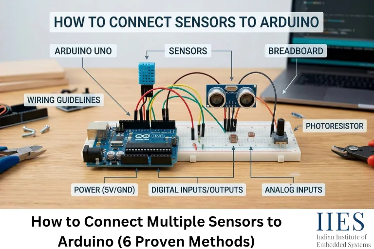
Know Your Sensor’s Communication Type Before You Wire Anything
Before touching a breadboard, sort every sensor in your project into one of five buckets. The bucket decides how many pins it costs you and which method below applies.
| Type | How it talks | Pins it needs | Common examples |
|---|
| Analog | Continuous voltage | 1 analog pin each | LDR, MQ-series gas sensors, potentiometers, thermistors |
| Digital (simple) | HIGH/LOW or timed pulse | 1–2 digital pins each | PIR, IR obstacle sensor, HC-SR04, DHT11/22 |
| I2C | Shared 2-wire bus + address | 2 pins total for ALL I2C devices | MPU6050, BMP280/BME280, SSD1306 OLED, DS3231 RTC |
| SPI | Shared 3-wire bus + chip-select | 3 shared pins + 1 CS pin each | SD card modules, NRF24L01, some ADCs |
| OneWire | Shared 1-wire bus + unique ID | 1 pin total for ALL devices | DS18B20 |
Once you know the buckets, “how do I fit 12 sensors on one Uno” usually turns into “which bucket actually needs help.”

Method 1: Direct Wiring for a Small Mixed Sensor Set
Use this when you have fewer than about 10 sensors and most are analog or simple digital types — no extra hardware needed, just budget your pins honestly before you start.
- Count digital pins used, including the 2 that HC-SR04-style sensors need.
- Reserve pins 0 and 1 if you’re using
Serial for debugging. - Reserve any pins your libraries claim automatically (SPI, I2C, tone()).
cpp
#define PIR_PIN 5
#define LDR_PIN A0

pinMode(PIR_PIN, INPUT);
bool motion = digitalRead(PIR_PIN);
int light  = analogRead(LDR_PIN);
This scales fine until you run out of pins — which is exactly when the next five methods start earning their keep.
Method 2: Multiple I2C Sensors on the Same Two Wires
I2C sensors share just two lines — SDA and SCL (A4/A5 on an Uno, pins 20/21 on a Mega) — and the master tells them apart using a 7-bit address. That gives you 128 possible addresses, though 16 are reserved, leaving 112 usable ones.
cpp
#include
#include
#include

Adafruit_MPU6050 mpu;   // default address 0x68
Adafruit_BMP280 bmp;    // default address 0x77

void setup() {
  Wire.begin();
  mpu.begin(0x68);
  bmp.begin(0x77);
}
Not sure what’s already on your bus? Run an I2C scanner before wiring anything new:
cpp
#include

void setup() {
  Wire.begin();
  Serial.begin(9600);
  for (byte addr = 1; addr < 127; addr++) {
    Wire.beginTransmission(addr);
    if (Wire.endTransmission() == 0) {
      Serial.print("Device found at 0x");
      Serial.println(addr, HEX);
    }
  }
}
void loop() {}
The I2C Pull-Up Trap Nobody Warns You About
Most I2C breakout boards already include their own onboard pull-up resistors on SDA and SCL. That’s fine with one or two modules — but wire five or six of them onto the same bus and those resistors sit in parallel, dragging the effective pull-up value low enough to distort the signal edges.
- If you’re combining several breakout boards, remove the pull-up resistors from all but one board.
- Standard external pull-ups are 4.7kΩ; a single pair on the whole bus is enough.
- Watch for a classic real-world collision: the DS3231 RTC and the MPU6050 (AD0 low) both default to address 0x68.
Method 3: Same I2C Address? Add a TCA9548A Multiplexer
Some sensors only offer one or two address-select options — not enough if your project needs four of the same module. A TCA9548A sits between the Arduino and your sensors, giving each one its own isolated channel.
- The multiplexer itself lives at address 0x70 by default (adjustable 0x70–0x77).
- It exposes 8 channels; you select one, then talk to whatever’s on it as if it were the only device on the bus.
cpp
#include

void tcaSelect(uint8_t channel) {
  if (channel > 7) return;
  Wire.beginTransmission(0x70);
  Wire.write(1 << channel);
  Wire.endTransmission();
}

void setup() {
  Wire.begin();
  tcaSelect(0);
  // talk to the sensor wired on channel 0
  tcaSelect(1);
  // talk to an identical sensor wired on channel 1
}
void loop() {}
Method 4: Out of Analog Pins? Add a CD4051 Multiplexer
The CD4051 is an 8-channel analog multiplexer: three select pins from the Arduino choose which of 8 inputs connects through to a single analog pin. Chain two together and you get 16 channels from one ADC input.
| CD4051 pin | Connects to |
|---|
| S0, S1, S2 | Any 3 Arduino digital pins |
| Z (COM) | One Arduino analog pin |
| Y0–Y7 | Your 8 sensor outputs |
| VDD / VSS | 5V / GND (single-supply mode) |
cpp
const int selectPins[3] = {2, 3, 4};
const int muxInput = A0;

int readMuxChannel(int channel) {
  digitalWrite(selectPins[0], bitRead(channel, 0));
  digitalWrite(selectPins[1], bitRead(channel, 1));
  digitalWrite(selectPins[2], bitRead(channel, 2));
  delayMicroseconds(5);       // let the switch settle
  return analogRead(muxInput);
}
The CD4051’s own on-resistance (roughly 125Ω) adds a small error with high-impedance sensors, usually negligible, but worth knowing if your numbers are slightly off versus a direct connection.

Method 5: Multiple SPI Sensors on One Bus
SPI devices share MOSI, MISO, and SCK (pins 11, 12, 13 on an Uno) but each one gets its own chip-select (CS) pin. Only one CS line goes LOW at a time — every other device on the bus must stay HIGH, or their outputs will collide.
cpp
#include

const int CS_SENSOR_A = 9;
const int CS_SENSOR_B = 10;

void setup() {
  pinMode(CS_SENSOR_A, OUTPUT);
  pinMode(CS_SENSOR_B, OUTPUT);
  digitalWrite(CS_SENSOR_A, HIGH);
  digitalWrite(CS_SENSOR_B, HIGH);
  SPI.begin();
}

uint8_t readSensor(int csPin, uint8_t reg) {
  digitalWrite(csPin, LOW);
  SPI.transfer(reg);
  uint8_t value = SPI.transfer(0x00);
  digitalWrite(csPin, HIGH);
  return value;
}
Need more than a couple of SPI devices and running low on pins? A 74HC138 decoder can generate several chip-select lines from just 3 Arduino pins — the same trick the CD4051 uses for analog inputs.
Method 6: Dozens of Sensors on One Wire (OneWire / DS18B20)
The DS18B20 temperature sensor is the odd one out in the best way: every unit ships with a unique 64-bit ROM address burned in at the factory, so dozens can share a single Arduino pin with no addressing conflicts at all.
- Only one 4.7kΩ pull-up resistor is needed for the whole bus, not one per sensor.
- Theoretical limits run past 60 devices; practical limits are closer to 10–20 because of bus capacitance over longer wires.
cpp
#include
#include

#define ONE_WIRE_BUS 4
OneWire oneWire(ONE_WIRE_BUS);
DallasTemperature sensors(&oneWire);

void setup() {
  Serial.begin(9600);
  sensors.begin();
  Serial.print(sensors.getDeviceCount());
  Serial.println(" DS18B20 sensors found");
}

void loop() {
  sensors.requestTemperatures();
  for (int i = 0; i < sensors.getDeviceCount(); i++) {
    Serial.print("Sensor "); Serial.print(i);
    Serial.print(": "); Serial.print(sensors.getTempCByIndex(i));
    Serial.println(" C");
  }
  delay(1000);
}
Bonus Trick: Reading Several Simple Sensors on ONE Analog Pin
This one rarely makes it into tutorials. If you have several simple on/off sensors, limit switches, basic threshold detectors – and you’re completely out of pins, wire each one through a different-value resistor into the same analog input. Each sensor produces a distinct voltage band when triggered, and your code decodes which one fired by checking which range the reading falls into. It won’t work for anything needing precise continuous values, but for a handful of on/off style inputs it can save several pins in a genuine pinch.
Choosing the Right Arduino Board for Your Sensor Count
| Board | Digital pins | Analog pins | Hardware serial ports | Best for |
|---|
| Uno R3 / R4 | 14 | 6 | 1 | Learning, small-to-medium sensor sets |
| Nano | 14 | 8 | 1 | Same budget as Uno, smaller footprint |
| Mega 2560 | 54 | 16 | 4 | Large sensor counts, multiple UART devices (GPS, etc.) |
| ESP32 | ~30+ usable | ~15+ (variant-dependent) | 3 | Same scale as Mega, plus built-in Wi-Fi/Bluetooth |
All four boards still give you exactly one practical I2C bus and one SPI bus each — extra pins help with analog and digital sensors directly, but I2C/SPI scaling still comes from Methods 3 and 5 above regardless of board.
Budgeting Power Before You Wire Anything Live
- Each I/O pin has a 40mA absolute maximum, 20mA recommended safe limit, don’t power sensors directly off a pin expecting more than that.
- Combined current across all I/O pins shouldn’t exceed roughly 200mA.
- As a rule of thumb, keep total sensor draw from the 5V pin under about 400-500mA when running off USB; go beyond that with a separate regulated supply.
- Any external supply must share a common ground with the Arduino — communication won’t work reliably otherwise, even if power looks fine.
- A 0.1µF ceramic capacitor across each sensor’s power and ground pins cuts down on the noise spikes that show up as jittery analog readings once a few modules are running together.
Writing Non-Blocking Code That Can Actually Handle Multiple Sensors
delay() freezes your entire sketch, which is fine for one sensor and a problem for five. Swap it for millis()-based timing so each sensor gets read on its own schedule without blocking the others:
cpp
unsigned long lastDHTRead = 0;
unsigned long lastDistanceRead = 0;

void loop() {
  unsigned long now = millis();

  if (now - lastDHTRead >= 2000) {       // DHT22 needs ~2s between reads
    lastDHTRead = now;
    float temp = dht.readTemperature();
  }

  if (now - lastDistanceRead >= 100) {   // ultrasonic can run much faster
    lastDistanceRead = now;
    long distance = readDistanceCM();
  }
}
Once you’re past 3–4 sensors, move each one’s variables into a small array or struct rather than copy-pasting a new pair of variables every time, it scales cleanly and stays readable.
Common Problems When You Add More Sensors (and How to Fix Them)
| Symptom | Likely cause | Fix |
|---|
| Random resets once everything’s connected | 5V rail current exceeded | External supply, measure actual draw |
| I2C device not found / NACK error | Address conflict or missing pull-ups | Run the I2C scanner, check the datasheet’s address pins |
| Analog readings drift when other sensors run | Shared noisy ground, long wires | Separate analog ground path, add decoupling caps |
| One sensor affects another’s behavior | Floating pins, library/timer conflict | Set explicit pinMode(), check for shared interrupt/timer use |
| Fine with 1–4 sensors, breaks at the 5th+ | 5V rail exceeded, not a code bug | Measure current, move to external power |
Complete Walkthrough: Wiring 5 Sensors to One Arduino Uno
A realistic mixed build, DHT22 (digital), HC-SR04 (2 digital pins), a PIR motion sensor (digital), an LDR (analog), and a BMP280 (I2C), all on one Uno, all non-blocking.
| Sensor | Type | Pin(s) | Power |
|---|
| DHT22 | Digital | 2 | 5V |
| HC-SR04 | Digital ×2 | Trig → 3, Echo → 4 | 5V |
| PIR (HC-SR501) | Digital | 5 | 5V |
| LDR (with divider) | Analog | A0 | 5V |
| BMP280 | I2C | SDA → A4, SCL → A5 | 3.3V — check your module before assuming 5V-tolerant |
cpp
#include
#include
#include

#define DHTPIN 2
#define DHTTYPE DHT22
#define TRIG_PIN 3
#define ECHO_PIN 4
#define PIR_PIN 5
#define LDR_PIN A0

DHT dht(DHTPIN, DHTTYPE);
Adafruit_BMP280 bmp;

unsigned long lastDHT = 0, lastDistance = 0, lastLight = 0, lastPressure = 0;
const unsigned long DHT_INTERVAL = 2000;
const unsigned long DISTANCE_INTERVAL = 200;
const unsigned long LIGHT_INTERVAL = 500;
const unsigned long PRESSURE_INTERVAL = 1000;

void setup() {
  Serial.begin(9600);
  dht.begin();
  pinMode(TRIG_PIN, OUTPUT);
  pinMode(ECHO_PIN, INPUT);
  pinMode(PIR_PIN, INPUT);
  if (!bmp.begin(0x76)) {
    Serial.println("BMP280 not found - check wiring/address");
  }
}

long readDistanceCM() {
  digitalWrite(TRIG_PIN, LOW);
  delayMicroseconds(2);
  digitalWrite(TRIG_PIN, HIGH);
  delayMicroseconds(10);
  digitalWrite(TRIG_PIN, LOW);
  long duration = pulseIn(ECHO_PIN, HIGH, 30000);
  return duration / 58;
}

void loop() {
  unsigned long now = millis();

  if (digitalRead(PIR_PIN) == HIGH) {
    Serial.println("Motion detected!");
  }

  if (now - lastDHT >= DHT_INTERVAL) {
    lastDHT = now;
    float h = dht.readHumidity();
    float t = dht.readTemperature();
    if (!isnan(h) && !isnan(t)) {
      Serial.print("Temp: "); Serial.print(t);
      Serial.print(" C, Humidity: "); Serial.print(h); Serial.println(" %");
    }
  }

  if (now - lastDistance >= DISTANCE_INTERVAL) {
    lastDistance = now;
    Serial.print("Distance: "); Serial.print(readDistanceCM()); Serial.println(" cm");
  }

  if (now - lastLight >= LIGHT_INTERVAL) {
    lastLight = now;
    Serial.print("Light level: "); Serial.println(analogRead(LDR_PIN));
  }

  if (now - lastPressure >= PRESSURE_INTERVAL) {
    lastPressure = now;
    Serial.print("Pressure: "); Serial.print(bmp.readPressure() / 100.0F);
    Serial.println(" hPa");
  }
}
Pre-Power-On Checklist
- All grounds, Arduino, sensors, and any external supply, tied together.
- Each sensor wired to its rated voltage, not assumed off the nearest rail.
- Pull-ups present where needed, and not duplicated across multiple I2C boards.
- Total current draw estimated against your power source’s real limit.
- No two sensors claiming the same pin, I2C address, or SPI chip-select line.
- Wiring double-checked against the actual datasheet, not memory of a similar project.

Key Takeaways
- Sort every sensor by communication type, analog, digital, I2C, SPI, or OneWire, before deciding how to wire it.
- I2C and OneWire are the cheapest ways to scale past the Uno’s 6-analog/20-digital pin ceiling.
- A TCA9548A solves same-address I2C conflicts; a CD4051 solves analog pin scarcity.
- Budget your 5V rail’s current before power-on, not after an unexplained reset.
- Replace
delay() with millis()-based timing once you’re juggling more than two sensors. - When in doubt about pin count, size up to a Mega or ESP32 before you’re halfway through wiring.