Because they enable microcontrollers to communicate with the analog world, analog-to-digital converters, or ADCs, are essential components of embedded systems. The ADC is a flexible and necessary peripheral for STM32 microcontrollers that enable the transformation of an analog voltage signal into a digital value that the microcontroller can process. The ADC is an essential part of your embedded project, whether you are reading sensor data, taking temperature readings, or keeping an eye on light levels.
This blog post will cover how to configure the ADC peripheral, read analog sensors using the STM32’s ADC, and write simple code to convert analog values to digital data.
A device that transforms an analog signal—typically a voltage—into a corresponding digital value is called an analog-to-digital converter, or ADC. The analog input is first sampled, quantized, and then transformed into a digital representation by the ADC. The ADC’s resolution (e.g., 8-bit, 12-bit, or 16-bit), which specifies the number of discrete values it can output, determines how accurate it is. For instance, an 8-bit ADC can only represent the analog input with 256 values, whereas a 12-bit ADC on an STM32 can represent it with 4096 possible values (0–4095).
ADC Resolution: STM32 ADCs have 12-bit resolution, which means that the analog value is transformed into one of 4096 distinct values (ranging from 0 to 4095). The amount of time the ADC spends sampling the input signal prior to conversion is known as the sampling time. Channels: STM32 microcontrollers have a number of ADC channels, each of which is associated with an analog input pin (PA0, PB1, for example). Conversion Modes: Regular conversions, continuous conversions, and injected conversions are among the modes that STM32 ADCs support.
DMA Support: Effective data transfer from the ADC to memory without CPU intervention is possible with Direct Memory Access (DMA). External Triggering: Timer settings, GPIO modifications, and software are examples of external events that can cause ADCs to activate.
Setting up and utilizing the ADC in STM32 requires a few key steps that can be completed either directly in code or via STM32CubeMX.
This is a broad overview of the procedure:
Setting up the ADC is simple with STM32CubeMX or STM32CubeIDE. The steps to accomplish this manually are as follows:
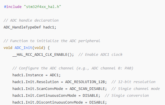
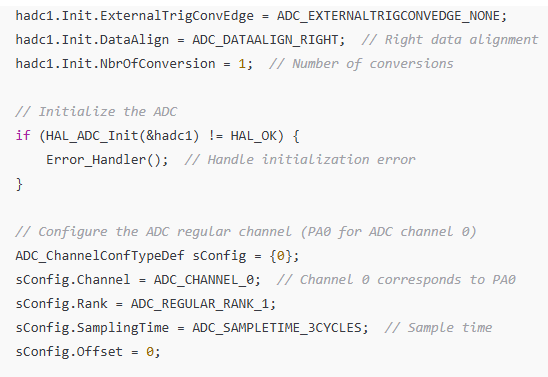
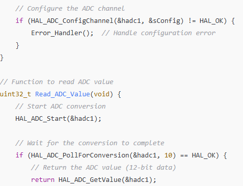
Here’s an example of how to read analog sensor data using the STM32’s ADC and Hardware Abstraction Layer (HAL): Example: Using ADC to Read an Analog Voltage


ADC Initialization The ADC peripheral is initialized with the configured parameters (resolution, sampling time, etc.) using the HAL_ADC_Init() function.
Which ADC channel to use—in this case, channel 0, which corresponds to PA0—is specified by the ADC_ChannelConfTypeDef struct.
ADC Value Reading: The conversion process is started by the HAL_ADC_Start() function. Until the conversion is finished (with a timeout), the HAL_ADC_PollForConversion() function waits.
The digital value that corresponds to the analog input is obtained using the HAL_ADC_GetValue() function.
Principal Loop: The conversion value can be utilized for additional processing (such as output via UART, control signals, etc.) after the ADC is read several times in the main loop.
To match the input voltage, it might be necessary to scale the raw ADC value, which for a 12-bit resolution ranges from 0 to 4095. The reference voltage, which is usually 3.3V or 5V, determines the scaling.
For instance, the following formula can be used to determine the corresponding voltage from the ADC value if the reference voltage is 3.3V and the ADC resolution is 12-bit:
To transform the ADC reading into a useful voltage or sensor value, you can incorporate this into your code.
For more effective data handling, you can use DMA (Direct Memory Access) to read data continuously from the ADC without causing any CPU blockages. DMA makes it possible to store ADC values straight into memory, freeing up the microcontroller to perform other tasks while gathering data.
In many embedded systems, reading analog sensors using the STM32’s ADC is a basic function. ADC peripherals from STM32 microcontrollers are flexible and support a range of configurations, including multiple input channels, resolution, and sampling time. You can interface with sensors to collect real-world data by properly configuring the ADC and writing basic code, which will increase the functionality and interactivity of your embedded system.
Indian Institute of Embedded Systems – IIES