The first aspect that comes to mind in the context of robot control is the regulation of DC motors. The integration of a DC motor with a microcontroller is a fundamental concept in the field of robotics. Connecting a DC motor to a microcontroller enables various functionalities, such as regulating the motor’s direction and adjusting its speed. This piece of writing explains the method for operating a DC motor utilizing the AT89C51 controller.
In basic terms, a DC motor is a machine that changes electrical energy from a direct current system into mechanical energy. It is essential for the industry at present to recognize the importance of this matter.
At a voltage of 5V, the maximum current output for a microcontroller pin is 15mA. Most DC motors have power requirements that surpass what a microcontroller can handle, and the back electromotive force produced by these motors may pose a risk of damaging the microcontroller. Therefore, directly connecting the DC motor to the controller is not advisable. Ensure that a motor driver circuit is placed between the DC motor and the controller for optimal performance.
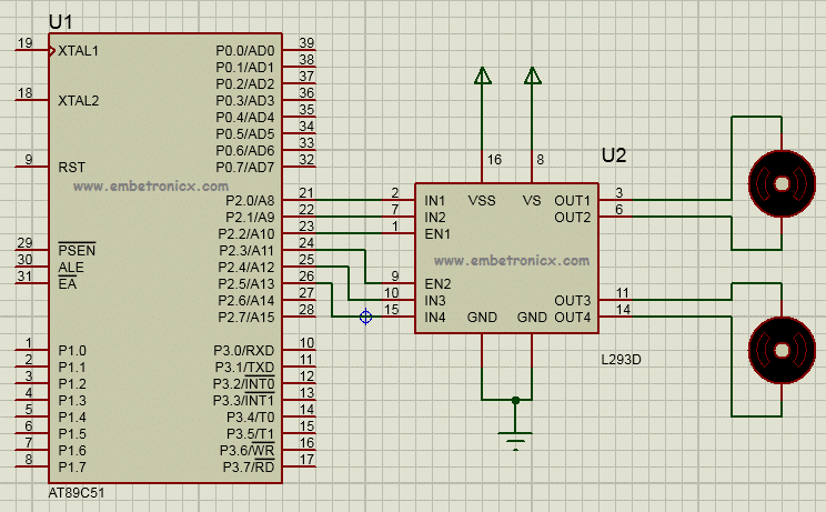
In this context, we are utilizing the L293D motor driver integrated circuit to control DC motors. With this IC, it is possible to control two DC motors concurrently. L293D is working on the principle of H-bridge circuit as follows.
The designation “H-Bridge” originates from the layout of the switching circuit responsible for managing the motor’s motion. It is often identified as the “Full Bridge.” There are four switching elements present in this circuit. The construction of H-bridges is achievable through the utilization of transistors, MOSFETs, and similar devices. Although it will be economical, there is a proposal to increase the dimensions of the design and the circuit board, which is often not preferred. Consequently, we can consider using a small 16-pin IC for this purpose.
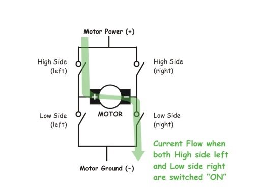
The figure illustrates four switching elements identified as follows:

Activating these switches in pairs results in a corresponding change in the motor’s direction. When we enable “High side left” and “Low side right,” the motor will turn in a forward direction. This occurs because the current from the power supply flows through the motor coil and is directed to ground through the switch located on the low side (right). The figure below demonstrates this.

Likewise, when we engage the low side (left) and the high side (right), the current reverses its flow, leading to the motor turning in the opposite direction. This describes the essential functioning of an H-Bridge. A brief truth table can also be created based on the H-Bridge switching mechanism described earlier.
High Left | High Right | Low Left | Low Right | Description |
On | Off | Off | On | Motor runs clockwise |
Off | On | On | Off | Motor runs anti-clockwise |
On | On | Off | Off | Motor stops or decelerates |
Off | Off | On | On | Motor stops or decelerates |
Table : Working of H-bridge circuit

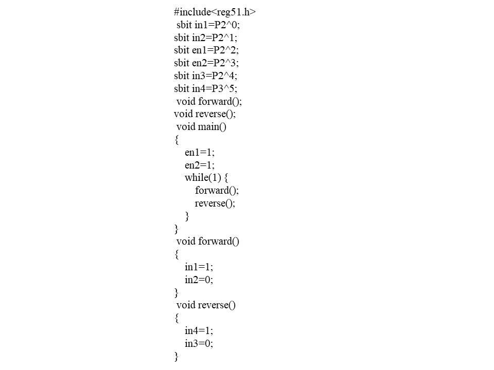
This code instructs the first motor to move forward, whereas the second motor is designated to move in the reverse direction.

Must Read: STM32 ADC: Analog Sensor Reading
Indian Institute of Embedded Systems – IIES