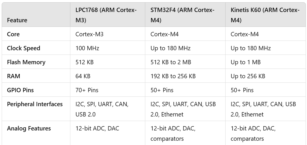
Based on the ARM Cortex-M3 core, the LPC1768 microcontroller features several integrated peripherals that are essential for a wide range of embedded applications. The most commonly used analog peripherals include analog-to-digital converters (ADCs) and digital-to-analog converters (DACs). These peripherals are essential for systems that include sensor data acquisition, signal processing, audio, motor control, and other real-time applications. This document provides information to help you get started with the LPC1768 ADC and DAC peripherals, including their functionality, configuration, and example code.
The LPC1768 features up to eight channels of 12-bit ADCs that can convert analog input signals into digital values. The ADC in the LPC1768 is used to sample analog signals from sensors (such as temperature, humidity, and pressure sensors), which are then processed in digital form by the microcontroller.
12-bit resolution: Converts analog signals into 12-bit digital values (range 0-4095).
Multiple input channels: The LPC1768 has up to eight analog input channels (depending on the case).
Conversion speed: The ADC can operate at speeds up to 400 kS/s (samples per second).
Single-ended or differential input: The ADC can handle both single-ended and differential signals. Selectable Reference Voltage: The reference voltage can be set, allowing flexibility depending on the application.
The LPC1768 contains a 12-bit DAC that can convert digital values (usually 0 to 4095) to analog signals. This is useful for applications such as audio generation, signal synthesis, and analog actuator control.
12-bit Resolution: Converts digital values to analog output with 4096 discrete levels.
Output Range: The DAC output range is typically 0V to the reference voltage (usually 3.3V). Output current capacity: Although the DAC can generate a small amount of current, it is sufficient for some applications such as audio output and small motor control.
Configuring the ADC: Before you can use the ADC with the LPC1768, you need to configure the following parameters: B. Input channel, reference voltage, and ADC conversion speed. Here is a step-by-step procedure on configuring and using the ADC.
Initializing the ADC: The ADC is controlled by the ADC0 module on the LPC1768. To use it, you need to enable the ADC0 peripheral in the control panel. Select Input Channel: The LPC1768 ADC has multiple input channels (ADC0.0 to ADC0.7). You can select the input channel based on the sensor or signal source.
Set ADC Conversion Mode: The ADC supports different operation modes.
Single Conversion: A single channel is sampled and converted.
Burst Conversion: Multiple channels are converted sequentially.
Start Conversion: After configuration, start the ADC conversion by manually triggering it or using an interrupt. Reading the Results: After the conversion is complete, the results can be read from the ADC Data Register.
Example Code for ADC:

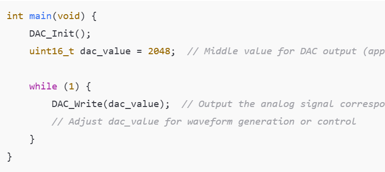
The DAC on the LPC1768 is very easy to use. It has 12-bit resolution and the output voltage is directly proportional to the digital input value you specify.
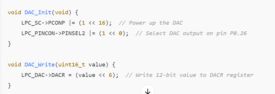
Initializing the DAC: Before you can use the DAC peripheral, you must activate it.
Writing a value to the DAC register: The DAC value is written to the DACR register. This register takes a 12-bit value (range 0-4095) and converts it to an analog voltage output.
Analog Signal Output: When a value is written to the DAC register, a corresponding analog voltage is output on the DAC pin.
Example Code for DAC:


Here are some common applications where ADCs and DACs are used together:
Sensor data acquisition and processing: An ADC can be used to read analog signals from sensors, and a DAC can output the processed result (e.g., a filtered or modified signal). For example, in a temperature measurement system, an ADC can convert a temperature sensor’s analog signal into digital form, and a DAC can output a control signal to control a fan or heater.
Signal conversion in audio systems: In audio applications, an ADC can digitize an audio signal from a microphone, and a DAC can generate an audio output to a speaker. The LPC1768’s ADC and DAC make it well-suited for creating cost-effective audio systems and generating test signals for audio devices.
Control systems: In systems such as motor control and robotics, an ADC reads feedback signals (e.g., position or speed sensors), and a DAC generates control signals (e.g., PWM duty cycle or analog actuator control voltages).
The integrated ADC and DAC peripherals in the LPC1768 provide powerful analog signal processing capabilities for embedded applications. With 12-bit resolution, multiple input channels for the ADC, and a simple yet effective DAC for analog output, the LPC1768 is ideal for systems requiring sensor data acquisition, signal generation, or motor control.
When properly configured, the ADC and DAC peripherals allow embedded applications to easily interact with analog devices, process signals, and generate real-time output.
Must Read: STM32 ADC: Analog Sensor Reading
Indian Institute of Embedded Systems – IIES