The Seven Segment Display (SSD) is a versatile output device that simplifies the presentation of numerical information. As a vital component in many embedded systems, the SSD pairs seamlessly with the 8051 Microcontroller Unit (MCU) to deliver real-time data to users. By understanding its functionality, you can easily interface this device to create efficient and visually appealing output solutions.
An SSD consists of seven distinct LED segments arranged to form numbers and basic characters. Operating on the same principles as LEDs, SSDs are available in two main configurations—Common Anode and Common Cathode. Each configuration influences how voltage is applied to illuminate the segments. When integrated with the 8051 MCU, these displays rely on precise control of their segments, making proper coding and connectivity essential for accurate outputs.
The Seven Segment Display, often referred to as SSD, serves as an output device. This can function as a tool for showcasing information. To support the user effectively, a system requires the right input and output devices, and the SSD contributes to this by delivering relevant information to the user. After gaining a proper understanding, you will find it simple to connect or interface with the 8051 MCU for output purposes.
This device serves as an output mechanism, and this is its visual representation. When you come across it, there is no need for confusion, as you will soon learn about it in a straightforward way.
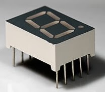
Seven Segment Display (SSD)
A Seven Segment Display is characterized by its seven segments that form the display. While these seven segments can create a range of shapes, their primary purpose is to convey numerical information. Here is how they will truly appear.

SSD Output (Numbers)
Consider the segments as distinct LEDs that have the capability to be switched ON or OFF. In terms of LEDs, you are aware that they have this particular look.
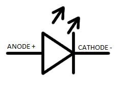
LED Symbol
It is important to understand that it will illuminate solely when the current travels from the anode to the cathode. Comprising individual LEDs, SSDs function on the same fundamental principle. In essence, they exist in two primary variations.
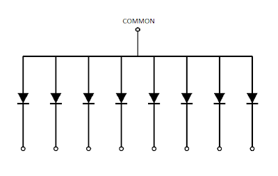
Common Anode
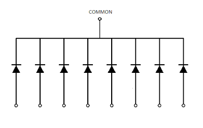
Common Cathode
In these circumstances, switching on an LED is a simple task, wouldn’t you agree? To enhance convenience, we designate a name to each segment of the SSD, allowing for straightforward dialogue regarding them. Presented here is the pin description for a standard SSD that you will encounter.
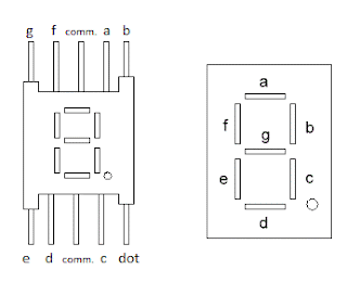
Pin Description of SSD
Suppose you want to enable segment ‘a‘
FOR COMMON CATHODE
FOR COMMON ANODE
Clearly, their functions are fundamentally different, making it important for you to be familiar with the specifics of your SSD. I believe you have grasped the concept by this point.
So far, you might have recognized that showcasing content on the SSD is fundamentally about arranging it in the correct order. The Segments are essentially a series of LEDs. It is crucial that you comprehend what is expected of you in this situation. As an illustration, segments ‘b’ and ‘c’ must be turned ON to show the digit ‘1’, as confirmed by the diagram provided above. A total of seven control lines are necessary to fully operate an SSD for display, which are designated as a, b, c, d, e, f, and g, with the dot being optional. Regarding the common pin, establish a connection to it.
The 74LS47 IC can be employed for interfacing with the 8051 microcontroller. Essentially, this component serves as a BCD to 7-segment Decoder/Driver, tailored for the operation of a seven-segment display (SSD). The purpose of this function is to generate the appropriate sequence for the SSD in response to a number from 0 to 9 sent by the MCU. Here is the truth table for a CC configuration.
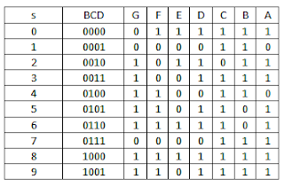
BCD to 7-SEGMENT Decoder Truth Table
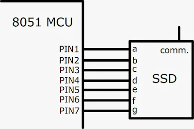
The connection between the SSD and the 8051 is direct, as the microcontroller does not possess the ability to harm it, and the program code can effectively manage the sequences, resulting in a more straightforward implementation.
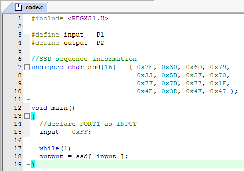
SSD Interface C language Code
We have now come to the end of our discussion, and I trust that this information has offered you a foundational perspective on the integration of an SSD with the 8051 microcontroller.
Must Read: STM32 ADC: Analog Sensor Reading
Indian Institute of Embedded Systems – IIES