
In the realm of microcontroller applications, input mechanisms play a vital role in bridging the gap between users and the system. From simple switches and push buttons to more complex interfaces, the methods for capturing user input are diverse. Among these, the numeric keypad stands out as a versatile input device, commonly used to facilitate data entry tasks such as entering codes, passwords, or commands.
A keypad, typically arranged in a 4×4 matrix of rows and columns, offers a straightforward yet effective design for user interaction. Each button in this matrix acts as a simple switch, establishing a connection between its corresponding row and column when pressed. However, the true intelligence of the keypad interface lies in the program code, which interprets button presses and communicates them to the microcontroller.
In the context of input to the microcontroller unit, which may originate from users or other sources, it involves a broader range of elements beyond simple ON/OFF switches or push buttons. There are various techniques available for gathering data from either users or the surrounding environment. As per the established criteria, users should be prepared to perform actions such as pressing buttons, toggling switches, or entering their username and password, among other interactions. Various sensing devices are implemented to detect shifts in the environment.
The term “keypad” refers to an input device, and it should not be mistaken for anything else, as it functions similarly to a keyboard. At this point, we are considering numerous buttons that can act as a keyboard for user data input into our microcontroller. These buttons may vary in both shape and size.
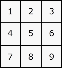
3×3 Numeric Keypad
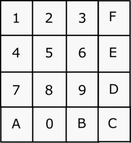
4×4 Hex Keypad
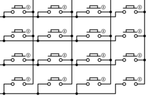
Keypad Internal Structure
This arrangement features four columns and four rows, resulting in a 4×4 structure. In principle, activating a specific button will merely establish a connection between the associated ROW and COLUMN lines, and that concludes the process. This is exactly the mechanism by which a keypad operates. A button does not possess knowledge of its meaning, including values like 1, 2, 3, and others. Likewise, a keypad does not comprehend the significance of its individual buttons, as it is fundamentally a straightforward circuit designed to house numerous buttons in one area.
At this point, we can confidently view our 4×4 HEX KEYPAD as a functional device.
The term 4×4 indicates that there will be four columns and four rows, as demonstrated. Based on the internal structure details, it is evident that activating button ‘5’ will connect R2 and C2 directly. Yet, concurrently, the most significant inquiry emerges. Which entity communicates to the microcontroller that button ‘5’ has been activated?
The solution is straightforward: Program Code.
It is the code that will keep track of all operations. The system needs to recognize a button press and evaluate the result. The integration of a keypad with a microcontroller unit is fundamentally a programming responsibility, since the code governs all interactions with the keypad.
8051 KEYPAD INTERFACE
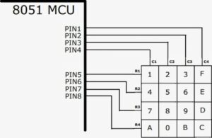
Each keypad pin should be linked to distinct pins of the 8051 microcontroller. The program code takes care of the rest, and I will provide a brief explanation of it now.
KEYPAD INTERFACE CODE
SCANNING is the term used to describe the act of reading from a keypad, which requires checking every key. The following outlines the essential steps for scanning a keypad.
Our approach involves starting at the first key, moving sequentially to the last key, and then returning to the first key to begin again. The procedure continues in this manner until a key press is detected, leading us to the next step of identifying the pressed key, though that is a different discussion.
Adjust all pins to the uppermost level
The first step is to configure all associated PINS to a HIGH level. The connection diagram mentioned earlier will serve as a visual aid to clarify this step. It is important to note that I have utilized the PIN state (HIGH or LOW) in place of the PIN number.
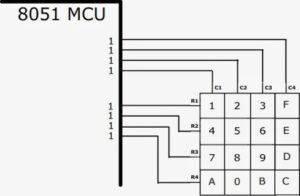
IDENTIFYING A ROW
Adjust the designated PIN to LOW in order to select a particular ROW. To demonstrate, we will configure the following PIN to a LOW state to choose the first ROW (R1).
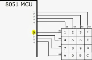
SELECTING 1ST ROW FOR SCANNING
Analyzing Columns
Verify the values of the PINS that are linked to the COLUMNS. Since we configured the PIN to HIGH in the first step, it will indicate a HIGH (1) reading when the button is unpressed, and a LOW reading when the button is pressed. When button ‘2’ is activated, the resulting output will be readily detectable.
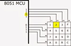
Output when Button 2 is Pressed
All keys can be examined in this way, by scanning the rows and columns, and this process persists until a key press is recognized. The speed of the microcontroller ensures that it never overlooks a key press. When the microcontroller initiates the scanning of the second ROW, a user can press a button in the first ROW. The benefit is that the system will promptly revert to the first ROW.
Programme for Keypad which is interfaced to 8051.
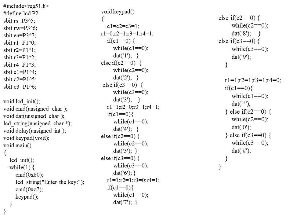
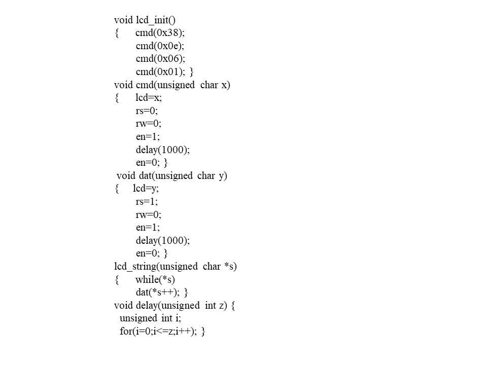
We have now come to the end of our discussion, and I trust that this information has offered you a foundational perspective on the integration of Matrix Key Pad with the 8051 microcontroller.
Must Read: STM32 ADC: Analog Sensor Reading
Indian Institute of Embedded Systems – IIES