Preface
Within an embedded system, the interaction between a microcontroller or microprocessor and external devices occurs through the use of input/output pins. The function of output pins is to convey data or information, whereas input pins serve to capture data or information. The microprocessor’s software executes at a much faster rate than the hardware interactions. Even a slight hardware delay of a few milliseconds can result in the processing of thousands of software instructions. For the most effective communication between hardware and software, a system referred to as interrupts is employed.
What is meant by the term interrupt?
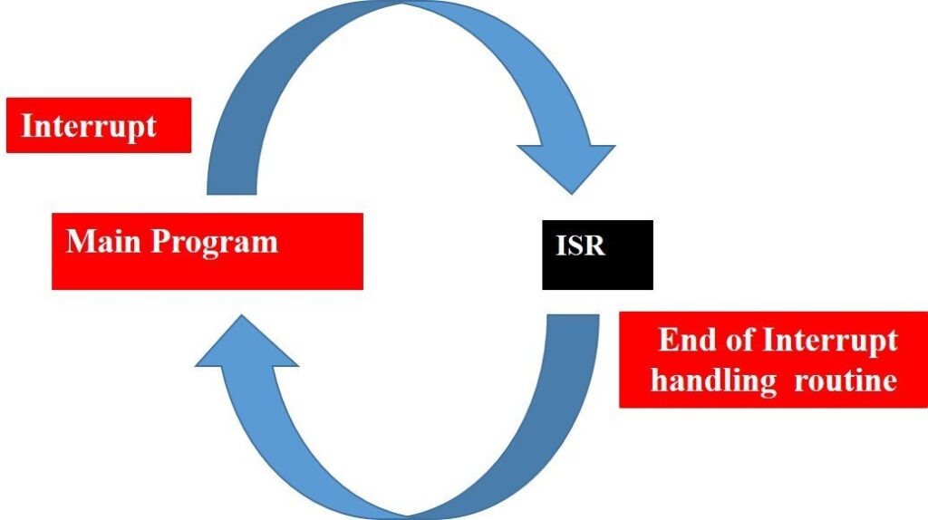
An interrupt serves as a hardware signal to the CPU, allowing it to temporarily halt the execution of the current program subroutine and initiate a different subroutine known as the ISR (interrupt service routine). The asynchronous nature of the ISR function call indicates that its execution relies on the occurrence of an interrupt. Typically, the position of this ISR function in various CPUs is indicated by a function pointer located in the Interrupt Vector Table.
An Overview on how Interrupts Operate
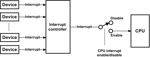
The CPU receives notification of an interrupt event from the interrupt controller. The function of the Interrupt Controller is to handle the interrupt hardware lines and to translate the incoming queries into a format recognizable by the CPU, utilizing the ISR instruction set. According to the offset number from the instruction branch, the CPU carries out the function found within the interrupt vector table.
Some microcontroller units (MCUs) employ an interrupt controller to manage the multiplexing of multiple hardware signals, facilitating communication with the CPU. The configurations of the interrupt controller can be either fixed or programmable, depending on the specific type of Interrupt Controller IP in use. Examples of interrupt management systems include NVIC (Nested Vectored Interrupt Controller), PMC (Programmable Interrupt Controller), and GIC (Generic Interrupt Controller).
Operational Interruptions
The Interrupt Operation consists of three primary elements, which are described below:
a. Establishing an Interrupt Configuration
b. Event Triggered by Hardware Interrupt
c. Carrying out an Interrupt
Establishing an Interrupt Configuration
There are several configurations available for the triggering and handling of an Interrupt signal. It is possible to set up an Interrupt trigger signal for digital IPs. For instance, SPI, I2C, and hardware timers, among others. Interrupts generally possess a sequence number, which is assigned to a specific IP configuration, an ISR function can be connected to each sequence. In the context of the vector table input, a sequence number is identified as the sequence.
Interrupts are configured in the code during the process of initializing the IPs. It confirms that both the IP Initialization and interrupt configuration are positioned together in the same area, to simplify the process of identifying and resolving issues in the code later on.
An event triggered by hardware that results in an interrupt
The interrupt lines within the MCU are arranged and associated with the respective IPs. Consider I2C or SPI as examples; in these cases, IPs share a direct connection to a hardware line that is linked to the interrupt controller. The configuration of the IPs allows for the trigger signal to be sent on the interrupt line, occurring at the beginning or end of a transaction. The CPU is notified of a system exception by the interrupt controller. The current program execution is paused by the CPU in accordance with the exception sequence, which then triggers the execution of the ISR function.
Performing an interrupt
By utilizing interrupts, we can incorporate two different contexts into our program. Initially, we have the main subroutine, succeeded by the ISR subroutine. Local variables and the return address are maintained within the program stack. Upon the activation of an interrupt, the existing program stack and return address details are preserved in a backup register or memory. The program counter then points to the address of the Interrupt Service Routine (ISR) for the next execution step.
An ARM microcontroller features two distinct stack pointers, namely the Main Stack Pointer (MSP) and the Process Stack Pointer (PSP). During the management of an interrupt, the Program Counter indicates the Main Stack Pointer. The PSP indicates the primary sub-program.