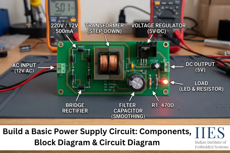
Why Is a Basic Power Supply Circuit Important?
Without a reliable power supply, even a perfectly designed embedded system may fail to operate correctly.
A properly designed power supply helps to:
- Convert AC mains voltage into usable DC voltage
- Protect electronic components from voltage fluctuations
- Reduce electrical noise and ripple voltage
- Improve overall circuit stability
- Increase system reliability
- Prevent unexpected resets in microcontrollers
- Supply clean voltage to sensors and communication modules
- Improve the lifespan of electronic components
Examples of devices using power supply circuits include:
- Embedded development boards
- Arduino projects
- STM32 systems
- ESP32 IoT devices
- Industrial automation equipment
- Medical electronics
- Consumer electronics
- Robotics
- LED lighting systems
- Security systems

What Is a Power Supply?
A power supply is an electrical device that delivers electrical energy to another electronic circuit or system.
Its primary function is to convert available electrical power into a voltage and current suitable for the connected device.
Depending on the application, a power supply may provide:
- AC output
- DC output
- Fixed voltage
- Variable voltage
- Regulated output
- Unregulated output
Common output voltages include:
What Is a Power Supply Circuit?
A power supply circuit is a combination of electronic components that converts electrical input into a stable and usable power source.
A basic power supply circuit generally performs four major operations:
- Step down high AC voltage
- Convert AC into DC
- Remove ripple voltage
- Maintain a constant output voltage
These operations are performed using four major components:
- Transformer
- Bridge Rectifier
- Filter Capacitor
- Voltage Regulator
Core Concepts
Before learning how to build a basic power supply circuit, it is important to understand a few fundamental concepts.
Alternating Current (AC)
Alternating current continuously changes its direction and magnitude over time.
Characteristics:
- Supplied by electrical mains
- Available as 230V AC in India
- Changes polarity every cycle
- Cannot directly power most electronic circuits
Examples:
- Household electrical outlets
- Industrial power distribution
Direct Current (DC)
Direct current flows in only one direction.
Characteristics:
- Constant polarity
- Stable voltage
- Required for electronic circuits
- Powers microcontrollers and digital ICs
Examples:
- Batteries
- USB power
- Mobile chargers
- Embedded development boards
Rectification
Rectification is the process of converting AC into DC.
It is performed using diodes arranged as:
- Half-wave rectifier
- Full-wave rectifier
- Bridge rectifier
A bridge rectifier is commonly used because it utilizes both halves of the AC waveform, resulting in higher efficiency and a smoother DC output after filtering.
Filtering
After rectification, the output contains ripple voltage.
A filter capacitor smooths the pulsating DC by storing electrical energy during voltage peaks and releasing it when the voltage drops.
Benefits include:
- Reduced ripple voltage
- Improved DC stability
- Better performance of electronic circuits
Voltage Regulation
Even after filtering, the output voltage can vary with input changes or load conditions.
A voltage regulator provides a constant output voltage.
Common regulator ICs include:
Regulator | Output Voltage |
7805 | 5V |
7809 | 9V |
7812 | 12V |
LM317 | Adjustable |
Components Required
The following components are commonly used to build a Basic Power Supply Circuit.
Component | Purpose |
Step-down Transformer | Reduces high AC mains voltage |
Bridge Rectifier | Converts AC into pulsating DC |
Filter Capacitor | Smooths the DC output |
Voltage Regulator | Provides stable output voltage |
Fuse | Protects against overcurrent |
Power Switch | Turns the circuit ON or OFF |
LED Indicator (Optional) | Indicates power availability |
Resistor | Limits current for LED |
PCB or Breadboard | Circuit assembly |
Block Diagram
      AC Mains

            │

            ▼

  Step-down Transformer

            │

            ▼

   Bridge Rectifier

            │

            ▼

   Filter Capacitor

            │

            ▼

   Voltage Regulator

            │

            ▼

     Stable DC Output
Working Principle
A basic power supply circuit converts AC into regulated DC through four sequential stages.
Step 1: AC Input
AC voltage enters from the mains supply. In India, this is typically 230V AC.
Step 2: Step-Down Transformer
Reduces high AC voltage to a safer level.
Example: 230V AC → 12V AC
Step 3: Bridge Rectifier
- Converts alternating current into pulsating direct current
- Uses four diodes arranged in a bridge configuration
- Utilizes both positive and negative half cycles of the AC waveform
Step 4: Filter Capacitor
- Charges during voltage peaks
- Discharges when voltage falls
- Reduces ripple voltage
- Produces smoother DC output
Step 5: Voltage Regulator
- Maintains a constant output voltage
- Compensates for input voltage variations
- Delivers stable power to the load
Final Output
The circuit provides a clean and regulated DC voltage suitable for powering embedded systems, sensors, development boards, and other electronic circuits.
Basic Power Supply Circuit Diagram
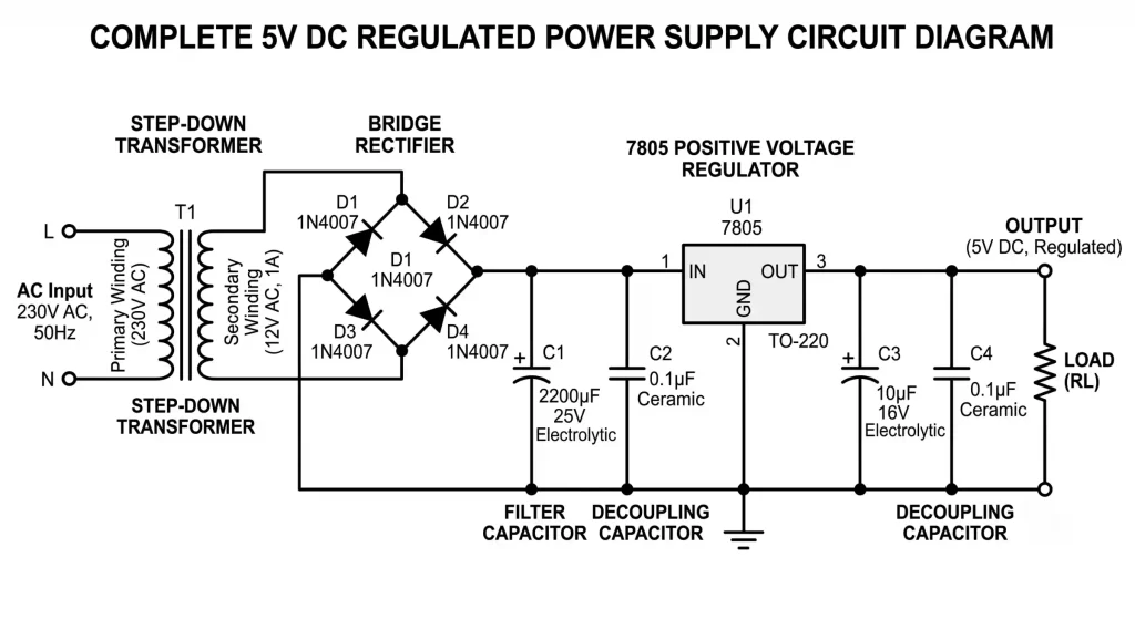
Complete 5V Regulated DC Power Supply Circuit featuring a 7805 linear voltage regulator.
How to Build a Basic Power Supply Circuit
Building a Basic Power Supply Circuit involves converting alternating current (AC) from the mains into a stable direct current (DC) output. Each stage has a specific purpose, and understanding these stages makes it easier to design, troubleshoot, and improve power supply circuits.
Note: If you are working with AC mains voltage (230V AC), always follow proper electrical safety practices. Beginners should use an isolated step-down transformer or a low-voltage AC source while learning.
Step 1: Select the Transformer
The transformer reduces the high AC mains voltage to a lower AC voltage suitable for the circuit.
Selection Tips
- Choose the secondary voltage based on the required DC output
- Select a transformer with sufficient current capacity
- Use an isolated transformer for safety
Example
Required DC Output | Recommended Transformer |
5V DC | 230V AC to 9V or 12V AC |
12V DC | 230V AC to 15V AC |
Keep in mind: After rectification and filtering, the DC voltage will be higher than the transformer’s RMS AC output. Ensure the voltage regulator can handle the input voltage.
Step 2: Build the Bridge Rectifier
The bridge rectifier converts the transformer’s AC output into pulsating DC.
Components Required
- Four rectifier diodes (such as 1N4007) OR
- One bridge rectifier module
Connection
- Connect the transformer secondary to the AC terminals
- The bridge rectifier provides positive (+) and negative (−) DC outputs
Why Use a Bridge Rectifier?
- Uses both halves of the AC waveform
- Provides better efficiency than a half-wave rectifier
- Produces a higher average DC output
Step 3: Add the Filter Capacitor
The rectified output still contains ripple voltage. A filter capacitor smooths this output.
Common Capacitor Values
Output Current | Typical Capacitor |
Up to 100 mA | 470 µF |
100–500 mA | 1000 µF |
500 mA–1 A | 2200 µF |
Important Points
- Connect the capacitor with the correct polarity
- Ensure the voltage rating is higher than the maximum DC voltage
- Electrolytic capacitors are commonly used for this stage
Step 4: Connect the Voltage Regulator
The voltage regulator provides a stable output even if the input voltage changes slightly.
Popular Voltage Regulators
IC | Output |
7805 | 5V |
7809 | 9V |
7812 | 12V |
LM317 | Adjustable Output |
Basic Connections
- Input pin → Filter capacitor output
- Ground pin → Circuit ground
- Output pin → Load
Additional Components
For improved stability, manufacturers typically recommend:
- Input bypass capacitor
- Output bypass capacitor
Always refer to the regulator’s datasheet for recommended values.
Step 5: Test the Output
Before connecting any electronic device:
- Verify the output voltage using a multimeter
- Check for correct polarity
- Ensure there are no loose connections
- Confirm that the regulator is not overheating
Only connect the load after confirming that the output voltage matches the expected value.

Advantages
A basic power supply circuit offers several benefits for learning and small electronic projects.
- Simple circuit design
- Easy to assemble
- Low component cost
- Reliable DC output
- Suitable for beginner electronics projects
- Easy to troubleshoot
- Widely used in educational laboratories
- Supports various voltage regulator ICs
- Can power microcontrollers and development boards
- Readily available components
Limitations
Although useful, a basic linear power supply has some limitations.
- Lower efficiency compared to switching power supplies (SMPS)
- Voltage regulators generate heat
- Bulky transformer increases circuit size
- Not suitable for high-power applications
- Output current is limited by the transformer and regulator
- Continuous operation may require heat sinks
Safety Precautions
Working with AC mains voltage requires extra care.
Follow these safety practices:
- Disconnect power before assembling the circuit
- Never touch exposed AC terminals
- Use an isolated transformer
- Install a fuse on the AC input
- Use insulated tools
- Verify wiring before switching on power
- Ensure proper grounding where required
- Replace damaged components immediately
- Do not exceed component voltage ratings
- Keep liquids away from the circuit
Real-World Applications
Basic power supply circuits are widely used across electronics and embedded systems.
- Embedded systems development
- Arduino projects
- STM32 development boards
- ESP32 IoT devices
- Robotics
- Industrial control circuits
- Sensor interfaces
- Laboratory power supplies
- LED lighting systems
- Home automation projects
- Consumer electronics
- Educational electronics kits
Best Practices
Following good design practices improves reliability and extends component life.
- Select components with adequate voltage and current ratings
- Use capacitors with suitable ripple current specifications
- Add bypass capacitors near the voltage regulator
- Use a heat sink when the regulator becomes hot
- Keep high-current traces short on the PCB
- Separate AC and DC sections to reduce electrical noise
- Label input and output terminals clearly
- Test the circuit without a load before connecting sensitive electronics
Common Mistakes
Choosing the Wrong Transformer
Why it happens: The transformer voltage or current rating is selected without calculating the circuit requirements.
Impact:
- Incorrect output voltage
- Regulator overheating
- Poor circuit performance
How to avoid it: Calculate the required voltage and current before selecting the transformer.
Reversing Capacitor Polarity
Why it happens: Electrolytic capacitors are connected incorrectly.
Impact:
- Capacitor damage
- Circuit failure
- Potential safety hazard
How to avoid it: Always verify the positive and negative terminals before soldering.
Ignoring Heat Dissipation
Why it happens: A voltage regulator is used without considering power loss.
Impact:
- Overheating
- Thermal shutdown
- Reduced component lifespan
How to avoid it: Use an appropriate heat sink when necessary and ensure adequate airflow.
Incorrect Bridge Rectifier Connections
Why it happens: The AC and DC terminals are mixed up during wiring.
Impact:
- No output voltage
- Component damage
- Circuit malfunction
How to avoid it: Double-check the bridge rectifier pinout before powering the circuit.
Testing and Troubleshooting
Testing each stage individually makes fault diagnosis much easier.
No Output Voltage
Possible Causes:
- Blown fuse
- Transformer not receiving power
- Incorrect wiring
- Faulty bridge rectifier
Solution: Measure the voltage at each stage, transformer output, rectifier output, capacitor output, and regulator output. This helps identify where the fault occurs.
Output Voltage Too Low
Possible Causes:
- Underrated transformer
- Excessive load current
- Faulty capacitor
- Defective regulator
Solution: Verify transformer rating, replace damaged components, and reduce the load temporarily to isolate the issue.
Excessive Ripple Voltage
Before Capacitor
/\/\/\/\/\
After Capacitor
──────────
Shows how the capacitor smooths the voltage.
Possible Causes:
- Filter capacitor value is too low
- Capacitor has degraded over time
Solution: Replace the capacitor with a suitable value and voltage rating.
Voltage Regulator Overheating
Possible Causes:
- High input-to-output voltage difference
- Excessive load current
- Inadequate cooling
Solution: Install a heat sink, reduce the input voltage if possible, or use a regulator with a higher current rating, consider a switching regulator for improved efficiency.
Performance Optimization Tips
A few design improvements can significantly enhance power supply performance.
- Choose low-ESR capacitors to improve filtering
- Keep AC and DC wiring separate to minimize electrical interference
- Use short and wide PCB traces for high-current paths
- Place bypass capacitors close to the voltage regulator pins
- Use quality rectifier diodes with appropriate current ratings
- Ensure adequate ventilation around heat-generating components
- Test the circuit under actual load conditions rather than only at no load
These practices help produce a more stable DC output, reduce noise, and improve the long-term reliability of the power supply circuit.

Conclusion
A Basic Power Supply Circuit is one of the most important building blocks in electronics and embedded systems. It converts alternating current (AC) into a stable direct current (DC) through voltage step-down, rectification, filtering, and regulation.
By understanding the function of each component, transformer, bridge rectifier, filter capacitor, and voltage regulator, you can design reliable power circuits for microcontrollers, sensors, communication modules, and other electronic applications.
Whether you are beginning your electronics journey or strengthening your embedded systems knowledge, mastering the basics of power supply circuits provides a solid foundation for designing and troubleshooting electronic hardware.