Hardware specifications
- Microcontroller LPC1768 (for example, through an evaluation board such as NXP LPCXpresso)
- Two DC motors for a differential drive Motor Driver Module (for controlling the motors, use L298N or L293D)
- Bluetooth Module (for remote control, HC-05 or HC-06) Chassis (wheeled robot body frame)
- Battery pack power supply (6V or 12V, depending on the needs of the motor)
Software prerequisites
- Keil uVision (IDE for LPC1768)
- Bluetooth terminal app (such as a serial terminal on a PC or Bluetooth Terminal on an Android device)
- LPC1768 firmware library (for motor control and peripheral initialization)
Building the Chassis and Connecting the Motors is Step 1.
Put the robot’s chassis together first, then attach the wheels and motors. A variety of robot kits are available, or you can construct your own chassis out of acrylic or plastic. The DC motors should then be connected to the motor driver (L298N or L293D). By acting as a conduit between the motors and the LPC1768, the motor driver enables the microcontroller to regulate the motors’ direction and speed.
To connect, follow these steps:
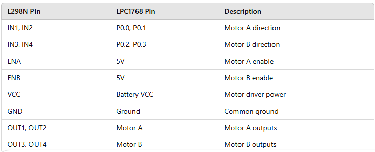
By applying HIGH or LOW signals to its input pins, the L298N driver module enables you to regulate the speed and direction of two motors.
Connecting the HC-05 Bluetooth Module in Step Two
A smartphone will be able to control the robot remotely thanks to the HC-05 Bluetooth module. To connect the Bluetooth module to the LPC1768, follow these steps:
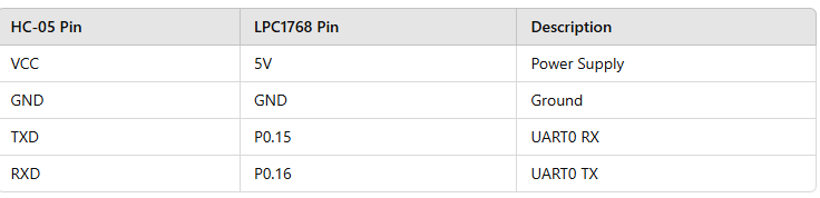
Note: The LPC1768 and the Bluetooth module communicate via UART. UART0 (pins P0.15 for TXD and P0.16 for RXD) is used in this example.
Step 3: Setting Up UART Communication on the LPC1768
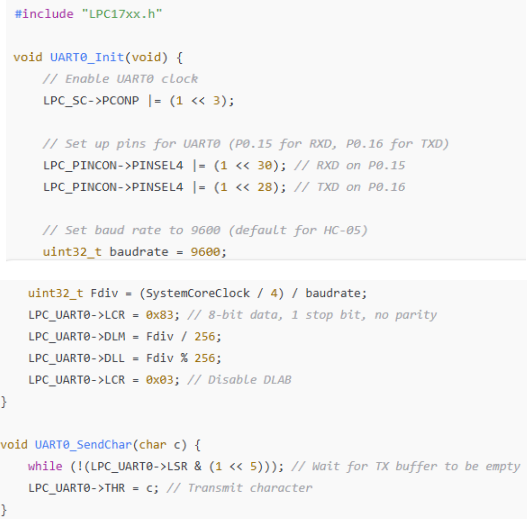
In order to connect to the HC-05 Bluetooth module, we must set up serial communication on UART0 on the LPC1768. This is an illustration of how to set up UART0 so that it can communicate with the Bluetooth module.

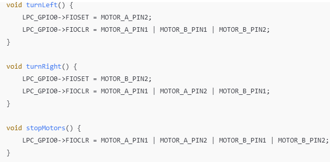
Step 4: Writing Motor Control Code
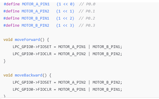
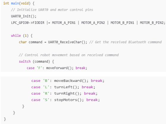
We will use Bluetooth to transmit commands from the smartphone to the LPC1768 in order to control the motors. The LPC1768 will direct the motor driver to move the robot in the desired direction based on the Bluetooth commands it has received. This is a basic program that controls the motors:
Step 5: Control and Pairing
Connect the Bluetooth module: To pair the HC-05 Bluetooth module with your smartphone, use the Bluetooth Terminal app. Send Instructions: Commands like “F” for forward, “B” for backward, “L” for left, “R” for right, and “S” for stop can be sent using the app.
Step 6: Testing and Last-Minute Modifications
Once everything is put together, use the battery to start the robot. Connect the HC-05 module to your smartphone by opening the Bluetooth terminal app. To move the robot left, right, forward, and backward, try sending commands. If required, modify the wiring and code to guarantee correct movement.
In conclusion
Using the LPC1768 microcontroller, DC motors, a motor driver, and Bluetooth connectivity, you have effectively constructed a basic robot. Bluetooth commands sent from a smartphone can be used to remotely control this robot. This project can be further developed by utilizing various motor control techniques, adding sensors for obstacle detection, or adding more sophisticated control features.
Upcoming Enhancements
Obstacle Detection: To prevent collisions, install an ultrasonic sensor.
Speed Control: To regulate motor speed, use pulse width modulation, or PWM.
Autonomous Navigation: Use sensors to carry out fundamental autonomous actions.