Hardware description
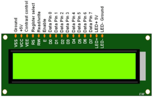
There are 16 pins available in most cases constate of power, data, and control.
«VSS: Ground (0V)
« VDD: Power supply (+5V)
+ VEE: Contrast adjustment voltage (can be used to control the display contrast)
« RS: Register Select (0 for command input, 1 for data input)
+ RW: Read/Write (0 for write, 1 for read)
+ E: Enable (Used to enable the data or command)
« DO0-D7: Data lines (8-bit parallel data lines used to send information)
* A: Anode (backlight anode, usually connected to +5V through a current-limiting
resistor)
K: Cathode (backlight cathode, connected to ground)
Functioning Principle
The functioning of the 16×2 LCD display involves the alteration of liquid crystals to generate text or graphical representations. Applying a voltage to the liquid crystal modifies its molecular orientation, impacting the polarization of light and causing it to become either transparent or opaque. The display controller interprets the data and creates the signals needed to regulate the liquid crystals, facilitating the display of characters or graphics on the screen.
Variants of LCD Modes
There are two fundamental modes in which LCD functions: 4-bit mode and 8-bit mode.
When operating in 4-bit mode, data is transmitted to the LCD module in a pair of consecutive nibbles. Initially, the higher nibble, made up of data lines D4 to D7, is transmitted, and this is succeeded by the lower nibble, which consists of data lines D0 to D3. By utilizing this configuration, we can transmit 8-bit data with only four data lines, which helps to save important I/O pins on the microcontroller.
The LCD can accept 8-bit data in a single transmission in 8-bit mode, employing all eight data lines (D0 to D7). Therefore, this mode enables a more rapid and effective data transfer process relative to the 4-bit mode. This method, however, demands additional I/O pins on the microcontroller, which could limit its applicability in projects that have a restricted number of available pins.
LCD Commands:
To present output on the screen, the LCD relies on a series of commands and instructions that are delivered by the microcontroller.
Clear Display (0x01): This command clears the entire display, resetting the cursor
position to the home position (0, 0).
Return Home (0x02): Sending this command moves the cursor to the home position
(0, 0) without clearing the display.
Entry Mode Set (0x04): This command determines the cursor movement direction
and whether the display should shift or not.
Display On/Off Control (0x08): This command controls the display, cursor, and
cursor blinking options.
Cursor or Display Shift (0x10): Used to shift the cursor or the entire display left or
right without changing the display data.
Function Set (0x20): This command sets the LCD data length (4-bit or 8-bit), number
of display lines, and font size.
Set CGRAM Address (0x40): This command sets the address of the Character
Generator RAM (CGRAM) for custom character creation.
Set DDRAM Address (0x80): This command sets the address of the Display Data
RAM (DDRAM), allowing data to be written to a specific location on the LCD.
Applications
16×22 LCD is used for a wide range of projects and industrial
Purpose:
1. Embedded systems:- these displays serve as user interfaces, providing status updates,
menu navigation, and interaction options.
2. Home automation:- LCD displays can be used to show temperature, humidity, and other
sensor readings in home automation projects.