Clipper and Clamper Circuits – A Complete Guide to Waveform Shaping

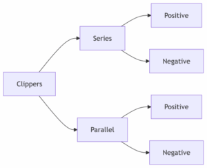
Classification of clipper circuits

Clipper and Clamper Circuits are fundamental in modern electronics, providing precise waveform shaping and signal conditioning. These circuits help control voltage levels by either limiting the amplitude of a signal or shifting its DC level without altering its basic shape.

Using simple components like diodes, capacitors, and resistors, clipper and clamper circuits are widely applied in voltage protection, DC restoration, and pulse shaping. From communication systems to biomedical and power electronics, mastering their operation is key to designing reliable and efficient electronic systems.

Why Waveform Modification Matters

In electronics, signals often need to be reshaped, limited, or shifted without changing their basic structure. This is where clipper and clamper circuits come into play. These simple yet powerful analog circuits are widely used in communication systems, power electronics, and signal conditioning circuits.

They ensure signals stay within safe voltage ranges, remove unwanted spikes, and restore lost DC levels, making them essential for both learning and practical engineering.


Register Now for Clipper and Clamper Circuits Course

Key Applications of Clipper and Clamper Circuits:

  • Signal conditioning circuits for ADC inputs.
  • Noise suppression in communication receivers.
  • DC restoration in video and TV signals.
  • Voltage protection circuits for sensitive devices.
  • Pulse shaping circuits in digital systems.

Clipper Circuits – Limiting Voltage Peaks

What Is a Clipper Circuit?

A clipper circuit (also known as a voltage limiter) is used to restrict the amplitude of a signal without distorting its overall shape. It ensures that signals do not exceed a specific voltage level.

Types of Clipper Circuits

  • Positive and Negative Clippers – Limit the positive or negative part of a waveform.
  • Biased Clipper Circuit – Uses a DC voltage source to shift the clipping level.
  • Diode Clipper Circuit – The most common form, implemented with one or more diodes.

Example – Noise Spike Clipper

  • Circuit: R = 1kΩ, D1/D2 = 1N4148 (Vf ≈ 0.7V)
  • Operation: Clips unwanted spikes above +0.7V and below -0.7V.

Basic Clipper Types

A clipper circuit removes (clips) a portion of the input signal without distorting the remaining part. Clippers are broadly classified into series and parallel types, and further into positive and negative clippers.

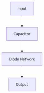
asic clamper circuit diagram showing input, capacitor, diode, and output waveform shift

Basic Clamper Operation

A clamper circuit shifts the entire input signal either upward or downward without changing its shape. It uses a combination of diodes, capacitors, and resistors to achieve this voltage level shift. 

clipper-circuits-classification 

Clamper Circuits – Shifting the Signal Level

What Is a Clamper Circuit?

A clamper circuit (also known as a DC restorer) shifts an entire signal up or down along the voltage axis without altering its shape.

Types of Clamper Circuits

  • Positive Clampers – Shift the signal upward.
  • Negative Clampers – Shift the signal downward.
  • Biased Clamper Circuit – Uses an external voltage source for controlled shifting.

Example – TV Sync Clamper

  • Circuit: C = 0.1μF, D = 1N914, R = 1MΩ.
  • Operation: Clamps sync pulses to 0V for proper synchronization.


Download Clipper and Clamper Circuits Brochure

Clipper vs Clamper – Quick Comparison

FeatureClipper CircuitsClamper Circuits
FunctionLimits voltage peaksShifts the waveform level
Key ComponentDiode clipper circuitDiode clamper circuit
ExampleZener diode clipper (voltage protection)Biased clamper circuit (controlled shifting)
ApplicationsVoltage protection circuits, pulse shaping circuitsSignal conditioning circuits, DC restoration

Practical Implementations

  • Zener Diode Clipper
    • Clip the voltage at the Zener breakdown level.
    • Common in voltage protection circuits.
  • Precision Active Clipper
    • Uses op-amps for accurate limits.
    • Ideal for signal conditioning in communication systems.

Applications of Clipper and Clamper Circuits

  • Clipper circuit applications: Noise reduction, voltage limiting in receivers, protection of MOSFET gates.
  • Clamper circuit applications: DC restoration in TV signals, baseline correction in biomedical instrumentation, synchronization in communication.

Troubleshooting Common Issues

  • Asymmetrical clipping → use matched diodes.
  • Drifting clamp level → check capacitor leakage.
  • No waveform shift → verify diode orientation.

Advanced Concepts

  • MOSFET-based clippers for high-speed digital circuits.
  • Adaptive clamping using comparators for varying signals.
  • Waveform shaping circuits in ultra-fast photonic systems.

Talk to Academic Advisor - Clipper and Clamper Circuits

Conclusion

Clipper and clamper circuits are fundamental building blocks in electronics. From voltage limiter circuits to DC restorers, they enable precise signal conditioning, voltage protection, and pulse shaping. By mastering these concepts, whether through diode clipper circuits, Zener diode clippers, or biased clamper circuits, you will gain the foundation needed for advanced design in embedded systems, communication, biomedical, and power electronic applications.

Frequently Asked Questions

A clipper circuit limits the amplitude of a waveform to a set voltage level, while a clamper circuit shifts the entire waveform up or down without altering its shape.

Clipper circuits are used in voltage protection, noise suppression, pulse shaping, and to prevent signals from exceeding safe voltage limits in communication and power electronics.

 Clamp circuits restore or shift the DC level of a waveform, which is crucial in applications such as TV signal synchronization and biomedical signal baseline correction.

Both circuits commonly use diodes, resistors, and capacitors. Clippers may also use Zener diodes for voltage regulation, while clampers rely more on capacitors for level shifting.

No. Clippers only remove parts of the signal beyond a set threshold, while clampers shift the entire waveform. The basic signal shape remains unchanged in both cases.

 A Zener diode clipper is often used in voltage protection circuits to prevent MOSFET gates or sensitive components from exceeding their voltage rating.

In television systems, a negative clamper circuit restores sync pulses to 0V for proper synchronization, ensuring a stable image display.