GSM Module Interfacing – A Complete Guide with LPC1768

GSM Module Interfacing with LPC1768 for IoT using SIM300 module

GSM Module Interfacing with LPC1768 plays a crucial role in embedded systems and IoT by enabling reliable and scalable mobile communication solutions. By using the LPC1768 microcontroller with GSM modules like SIM300, and leveraging AT commands for GSM modules along with standard communication protocols, developers can create real-time SMS, call, and remote monitoring systems. Understanding the GSM module working principle is essential for building efficient and high-performance IoT and embedded applications.

GSM Module Interfacing empowers developers to send SMS, make calls, and integrate remote monitoring with LPC1768. From SIM300 GSM module setup to AT command execution, mastering these fundamentals ensures robust, scalable, and reliable communication for IoT and embedded projects.

What Is GSM Module Interfacing?

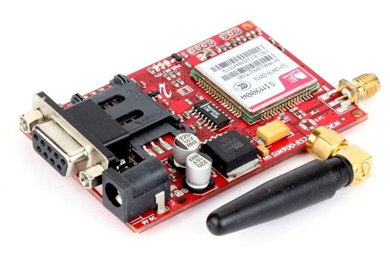
GSM (Global System for Mobile Communication) is the standard used in most mobile networks worldwide. It enables voice calls, text messaging, and basic data communication. GSM Module Interfacing refers to connecting a microcontroller, such as LPC1768, to a GSM module like the SIM300 GSM module so it can interact with mobile networks and exchange data.
Key purposes of GSM module interfacing include sending and receiving SMS automatically, initiating voice calls from a controller, monitoring and alerting in IoT-based systems, and remote data collection in industrial applications.


Register Now for GSM Module Interfacing Course

GSM Module vs GSM Mobile

Understanding the difference is important:

FeatureGSM MobileGSM Module
PurposePersonal communicationMicrocontroller communication
Requires an external controllerNoYes
AT Command supportLimitedFull support via GSM at the command list
FlexibilityLowHigh (IoT, monitoring, automated SMS)
ExamplesAny smartphoneSIM300 GSM module, SIM800

GSM Module Working Principle

The GSM module’s working principle is based on receiving AT commands from a microcontroller, executing them, and responding with data or confirmation. The module manages network protocols and low-level cellular communication, simplifying the process for developers.

  • The module is powered using a voltage supply (3.2V–4.5V for SIM300).
  • Communication is established over UART using a specific GSM module pin configuration.
  • AT commands are sent to perform operations such as sending SMS, making calls, or querying network status.
  • Responses are read from the module to confirm execution.
  • By using AT commands, the microcontroller does not need to handle the complex GSM communication protocols.

GSM Module Features and SIM300 Overview

GSM Module Features

The SIM300 GSM module is a widely used tri-band GSM/GPRS solution. Key features include:

  • Single supply voltage: 3.2–4.5V
  • Low power consumption in sleep mode (~2.5 mA)
  • Tri-band support for 900/1800/1900 MHz networks
  • Supports SIM cards with 1.8V and 3V
  • Compact plug-in module for easy interfacing
  • Can send/receive SMS and make calls using AT commands
  • Supports GPRS for IoT data transfer

AT Commands for GSM Module

AT commands allow you to control GSM modules. “AT” stands for Attention and originates from the Hayes command set. Key operations include:

  • Dial numbers
  • Send and read SMS
  • Configure the module
  • Query network status
AT CommandFunction
ATDDial number
AT+CMGFSet SMS text mode
AT+CMSSSend SMS from storage
AT+CMGLList SMS messages
AT+CMGRRead SMS message
AT+CSCA?Get SMS Service Centre Address
AT+CPMSSelect memory storage
AT+IPR=0Set automatic baud rate
AT+SMGFChoose PDU or Text mode

Interfacing the GSM Module with the LPC1768

Proper interfacing ensures reliable UART communication between LPC1768 and GSM modules.

Interfacing of GSM Module

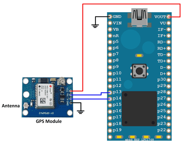
  • Pin Assignment:
    GSM UARTLPC1768 Controller
    TXD1P0.16
    RXD1P0.15
  • Steps to Interface:
    1. Initialize UART (UART1 recommended) with proper PINSEL and baud rate settings.
    2. Transmit AT commands using the UART.
    3. Provide delays between commands to allow module response.
    4. Receive responses to confirm execution.

Example: Sending SMS Using GSM Module

#include 

int main() {
    // Initialize UART
    // Send AT commands to select SMS mode
    // Send SMS using AT+CMGS
    return 0;
}


Download GSM Module Interfacing Brochure

Common Mistakes to Avoid

  • Ignoring module responses → leads to failed communication.
  • Wrong GSM module pin configuration → UART errors.
  • Using incorrect baud rates → module may not respond.
  • Forgetting correct voltage supply (3.2–4.5V) → module malfunction.
  • Not handling AT command errors → unstable operation.

When to Use GSM Modules

  • Remote monitoring or alerts
  • Implementing GSM-based monitoring systems
  • Automating SMS notifications or call alerts
  • Integrating mobile communication into IoT projects

Conclusion

GSM Module Interfacing with LPC1768 is essential for building reliable embedded systems and IoT applications. By understanding the GSM module working principle, using correct AT commands, and following proper pin configuration, developers can send and receive SMS, make voice calls, implement remote monitoring, and build automated IoT systems.

Talk to Academic Advisor - GSM Module Interfacing

Frequently Asked Questions

 It is connecting a microcontroller to a GSM module to send/receive messages or data over mobile networks.

The SIM300 GSM module is widely used due to its tri-band support and compact size.

AT commands are instructions sent to the module to perform operations like sending SMS or making calls.

Yes, they are ideal for GSM-based monitoring systems, remote notifications, and automated alerts.


A GSM module requires a microcontroller to function and offers full AT command control for automation, whereas mobile phones are standalone devices.