Step-by-Step Working of 8051 Interrupts
1. Interrupt Flag is Set
When an event occurs, the corresponding flag bit is set automatically.
| Event | Flag Bit |
|---|
| External INT0 | IE0 |
| Timer0 overflow | TF0 |
| External INT1 | IE1 |
| Timer1 overflow | TF1 |
| Serial Rx / Tx | RI / TI |
2. Global Interrupt Enable (EA Bit)
The CPU checks the EA bit (IE.7):
EA = 1 → Interrupts enabled
EA = 0 → All interrupts disabled
3. Individual Interrupt Enable Check
| Interrupt | Enable Bit |
|---|
| INT0 | EX0 |
| Timer0 | ET0 |
| INT1 | EX1 |
| Timer1 | ET1 |
| Serial | ES |
4. Interrupt Priority Check (IP Register)
If multiple interrupts occur simultaneously:
IP bit = 1 → High priority
IP bit = 0 → Low priority
High-priority interrupts can interrupt low-priority ISRs.
5. Saving Program Counter
The current Program Counter (PC) value is pushed onto the stack.
6. Jump to Interrupt Vector Address
| Interrupt | Vector Address |
|---|
| INT0 | 0003H |
| Timer0 | 000BH |
| INT1 | 0013H |
| Timer1 | 001BH |
| Serial | 0023H |
7. Execution of ISR
The Interrupt Service Routine executes the required task.
8. RETI – Return from Interrupt
The RETI instruction:
Pops the saved PC from the stack
Returns control to the main program

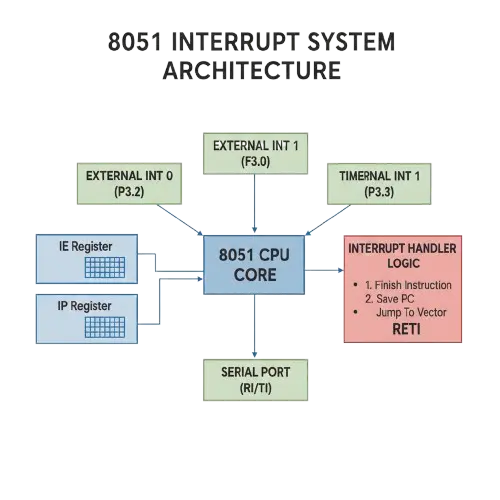
Interrupt Handling Mechanism in 8051
| Step | Operation |
|---|
| 1 | Event occurs and flag is set |
| 2 | CPU checks IE register |
| 3 | Priority is verified |
| 4 | Program Counter saved |
| 5 | CPU jumps to ISR |
| 6 | ISR executes |
| 7 | RETI returns control |
Programming Example – Timer0 Interrupt
ORG 0000H
LJMP MAIN

ORG 000BH
LJMP TIMER_ISR

MAIN:
MOV TMOD, #01H
MOV TH0, #0FCH
MOV TL0, #18H
SETB TR0
SETB ET0
SETB EA
SJMP $

TIMER_ISR:
CLR TF0
MOV TH0, #0FCH
MOV TL0, #18H
RETI
END
Solved Example – LED Blinking Using Timer0 Interrupt
ORG 0000H
LJMP MAIN

ORG 000BH
LJMP TIMER0_ISR

MAIN:
MOV TMOD, #01H
MOV TH0, #0FCH
MOV TL0, #018H
SETB P1.0
SETB ET0
SETB EA
SETB TR0

HERE:
SJMP HERE

TIMER0_ISR:
CLR TR0
CLR TF0
MOV TH0, #0FCH
MOV TL0, #018H
CPL P1.0
SETB TR0
RETI
END
Real-Time Example – Frequency Measurement Using Timer1 Interrupt
ORG 0000H
LJMP MAIN

ORG 001BH
LJMP TIMER1_ISR

MAIN:
MOV TMOD, #50H
MOV TH1, #00H
MOV TL1, #00H
SETB ET1
SETB EA
SETB TR1

HERE:
SJMP HERE

TIMER1_ISR:
CLR TR1
MOV P1, TL1
MOV TH1, #00H
MOV TL1, #00H
SETB TR1
RETI
END
Real-Time Applications of 8051 Interrupts
- Digital clocks
- LED blinking systems
- Industrial timing systems
- RPM and speed measurement
- Task scheduling and multitasking
Advantages of Using Interrupts in 8051
- Faster response time
- Efficient CPU utilization
- No continuous polling
- Ideal for real-time systems
Conclusion
Interrupts are the backbone of real-time embedded systems. By using the interrupt structure, IE register, IP register, vector table, and ISR routines, the 8051 microcontroller can respond instantly to external and internal events without wasting CPU resources. Mastering 8051 interrupts is essential for building reliable, efficient, and industry-ready embedded applications.