Why Use ADC with DMA Instead of Polling or Interrupts?
Traditional ADC polling and interrupt-based sampling consume CPU cycles and introduce latency. Using ADC with DMA solves these limitations.
Key Advantages of ADC with DMA
- Eliminates CPU overhead during sampling
- Enables continuous high-speed data transfer
- Reduces interrupt latency and jitter
- Improves system stability and reliability
- Lowers overall power consumption
- Ideal for real-time signal processing
This approach is widely used in high-speed sensor data acquisition systems, embedded data logging, and industrial monitoring applications.
Applications of Embedded Data Acquisition Systems
An embedded data acquisition system using LPC1768 ADC with DMA is commonly used in:
- Industrial automation and control systems
- IoT sensor monitoring and gateways
- Medical instrumentation
- Audio and digital signal processing
- Power and energy measurement systems
- Environmental and long-term data logging
These applications require deterministic, low-latency ARM Cortex-M data acquisition.
LPC1768 ADC and DMA Hardware Overview
The LPC1768 is an ARM Cortex-M3 microcontroller featuring a high-performance ADC and a General-Purpose DMA (GPDMA) controller.
LPC1768 ADC Features
- 12-bit resolution
- 8 multiplexed input channels
- Burst mode for continuous sampling
- Hardware trigger support
- Internal temperature sensor
LPC1768 GPDMA Features
- High-speed peripheral-to-memory transfers
- Minimal CPU intervention
- Circular buffer capability
- Interrupt-based transfer completion
- Ideal for real-time data capture
Using GPDMA with ADC allows continuous sampling without CPU bottlenecks.
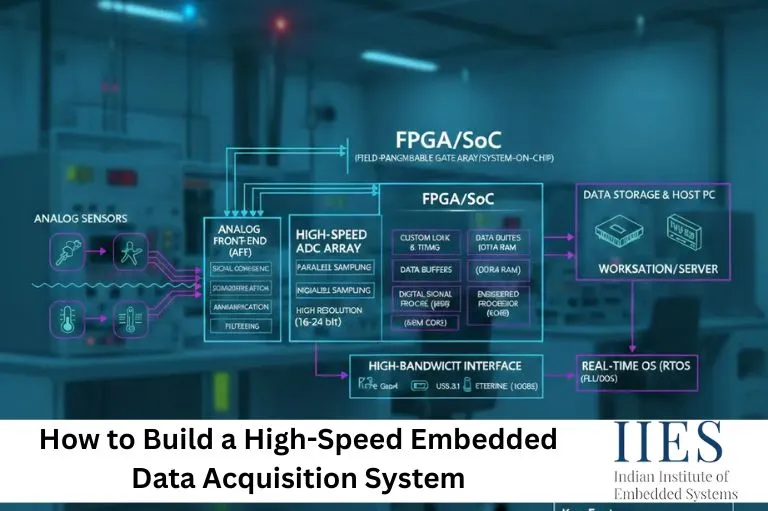
System Architecture of ADC with DMA
Data Flow Architecture:
Sensor → ADC → DMA → RAM Buffer → Processing → Storage / Display
DMA transfers ADC conversion results directly into RAM, making the system suitable for high-speed and long-duration data acquisition.

Step-by-Step ADC with DMA Configuration (LPC1768)
Step 1: Enable ADC and DMA Modules
#include "LPC17xx.h"
#define ADC_BUFFER_SIZE 1024

volatile uint16_t adc_buffer[ADC_BUFFER_SIZE];
volatile uint8_t dma_complete = 0;

void init_adc_dma(void) {
    LPC_SC->PCONP |= (1 << 12) | (1 << 29); LPC_PINCON->PINSEL1 &= ~(3 << 14); LPC_PINCON->PINSEL1 |= (1 << 14); LPC_PINCON->PINMODE1 |= (1 << 15);
}
This powers up the ADC and GPDMA peripherals and configures the ADC input pin.
Step 2: Configure ADC for DMA and Burst Mode
void configure_adc_for_dma(void) {

    LPC_ADC->ADCR = (1 << 0) |     // Select ADC channel 0
                    (4 << 8) |     // ADC clock divider
                    (1 << 21) |    // Enable ADC
                    (1 << 24); // Burst mode LPC_ADC->ADINTEN = 0;
    LPC_ADC->ADSTAT = 0xFF;
}
Burst mode enables continuous ADC conversions, making it ideal for DMA-driven sampling.
Step 3: Configure DMA Channel for ADC Transfer
void setup_dma_channel(void) {

    LPC_GPDMA->CH[0].CCONFIG = 0;

    LPC_GPDMA->CH[0].CSRCADDR  = (uint32_t)&LPC_ADC->ADGDR;
    LPC_GPDMA->CH[0].CDESTADDR = (uint32_t)adc_buffer;

    LPC_GPDMA->CH[0].CCONTROL =
        (ADC_BUFFER_SIZE << 0) |
        (2 << 18) |   // Transfer width: 16-bit
        (1 << 21) |   // Source increment disabled
        (1 << 27) |   // Destination increment enabled
        (1 << 31); // Terminal count interrupt enable LPC_GPDMA->CH[0].CCONFIG =
        (1 << 0) |    // Enable channel
        (1 << 1) |    // Peripheral-to-memory
        (1 << 11);    // ADC DMA request

    NVIC_EnableIRQ(DMA_IRQn);
}
This configures peripheral-to-memory DMA transfer from ADC to RAM.
Step 4: Start Continuous ADC Sampling
void start_adc_dma_sampling(void) {

    dma_complete = 0;

    LPC_ADC->ADCR |= (1 << 16); // Start ADC LPC_GPDMA->CH[0].CCONFIG |= (1 << 0);
}
This enables uninterrupted high-speed sampling.
DMA Interrupt Handler (Continuous Data Logging)
void DMA_IRQHandler(void) {

    if (LPC_GPDMA->INTSTAT & (1 << 0)) { if (LPC_GPDMA->INTTCSTAT & (1 << 0)) { dma_complete = 1; LPC_GPDMA->INTTCCLEAR = (1 << 0); process_adc_buffer(); restart_dma(); } if (LPC_GPDMA->INTERRSTAT & (1 << 0)) { handle_dma_error(); LPC_GPDMA->INTERRCLEAR = (1 << 0);
        }
    }
}
This ensures continuous embedded data logging with minimal CPU usage.
Real-World Example: Audio Data Acquisition (44.1 kHz)
void setup_audio_sampling(void) {

    LPC_TIM0->PR  = 0;
    LPC_TIM0->MR0 = 2267;
    LPC_TIM0->MCR = 3;

    LPC_ADC->ADCR = (1 << 0) |
                    (4 << 8) |
                    (1 << 16) |
                    (1 << 21);

    setup_circular_dma_buffer(1024);

    NVIC_SetPriority(DMA_IRQn, 1);
}
This configuration enables real-time audio capture using ADC with DMA.
Performance Optimization Best Practices
- Use circular DMA buffers
- Minimize DMA interrupt processing time
- Optimize ADC clock frequency
- Use sleep modes during DMA transfers
- Apply filtering in post-processing
These techniques significantly improve high-speed data acquisition system reliability.

Advantages of an Embedded Data Logging System Using DMA
- Continuous real-time sampling
- Very low CPU usage (up to 70–90% reduction vs interrupts)
- Higher data accuracy and consistency
- Scalable and modular architecture
- Suitable for long-term operation
Conclusion
An Embedded Data Acquisition System using ADC with DMA on LPC1768 provides a high-speed, low-power, and reliable solution for real-time signal acquisition.
By combining the LPC1768 ADC with GPDMA, developers can build professional ARM Cortex-M3 data acquisition systems suitable for industrial, medical, audio, and IoT applications—without wasting CPU resources.
This architecture represents a best-practice approach for modern embedded system design.