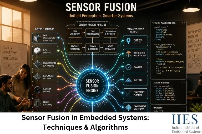
What Is Sensor Fusion in Embedded Systems?
Sensor fusion is the process of collecting, processing, and combining measurements from multiple sensors to estimate a physical condition or understand an environment.
Instead of depending on one sensor, an embedded system uses information from different sensors to improve measurement accuracy and reliability.
For example, consider a motion-tracking device containing:
- Accelerometer: Measures linear acceleration.
- Gyroscope: Measures angular velocity.
- Magnetometer: Measures magnetic field direction.
Each sensor provides different information. When their measurements are combined, the system can estimate its orientation more effectively.
This process is called multi-sensor data fusion.
Simple Example of Sensor Fusion
Imagine a drone flying in the air. It needs to maintain a stable position and orientation.
An accelerometer detects changes in movement, while a gyroscope measures rotational movement. A magnetometer helps determine heading direction.
If the drone uses only the gyroscope, small measurement errors can accumulate over time. If it uses only the accelerometer, sudden movements and vibrations can affect orientation estimates.
By combining all three sensors through a sensor fusion algorithm, the flight controller can calculate a more reliable orientation estimate.
Why Is Sensor Fusion Important in Embedded Systems?
Individual sensors cannot always provide complete or reliable information. Sensor fusion addresses these limitations by combining complementary measurements.
Some important benefits include:
- Improved measurement accuracy: Combining measurements from multiple sensors can reduce the influence of individual sensor errors.
- Better reliability: If one sensor produces noisy or unreliable readings, information from other sensors can help maintain a useful estimate.
- Reduced measurement noise: Filtering algorithms help remove unwanted variations from sensor readings.
- Real-time decision-making: Embedded processors can combine sensor information to make decisions within strict timing requirements.
- Better environmental awareness: Multiple sensors allow devices to understand movement, distance, temperature, pressure, and other physical conditions.
- Improved system performance: Sensor fusion supports more dependable operation in robotics, automotive electronics, industrial automation, and IoT devices.
Common Sensors Used in Multi-Sensor Data Fusion
Different embedded applications require different sensor combinations. Understanding the characteristics of individual sensors is essential before implementing sensor fusion.
| Sensor | What It Measures | Common Applications |
| Accelerometer | Linear acceleration | Motion detection, tilt measurement |
| Gyroscope | Angular velocity | Rotation and orientation tracking |
| Magnetometer | Magnetic field | Compass and heading estimation |
| GPS | Geographic position and speed | Navigation and tracking |
| LiDAR | Distance using laser light | Robotics and autonomous vehicles |
| Ultrasonic sensor | Distance using sound waves | Obstacle detection |
| Camera | Visual information | Object detection and tracking |
| Temperature sensor | Temperature | Industrial monitoring |
| Pressure sensor | Pressure | Automotive and industrial systems |
For example, an autonomous mobile robot may combine camera, LiDAR, IMU, and wheel encoder measurements to estimate its position and detect nearby obstacles.

How Does Sensor Fusion Work?
Sensor fusion generally involves collecting measurements, preprocessing the data, aligning measurements in time, combining the information, and generating a final estimate.
A typical sensor fusion architecture follows these stages:
1. Sensor Data Acquisition
The embedded controller collects data from connected sensors using communication interfaces such as:
For example, an STM32 microcontroller may communicate with an accelerometer through I2C and receive GPS data through UART.
2. Data Preprocessing
Raw sensor readings may contain noise, offset errors, scaling differences, and unwanted variations.
Before combining the readings, the system may perform:
- Sensor calibration
- Noise filtering
- Offset correction
- Unit conversion
- Range validation
This step helps ensure that sensor measurements are suitable for further processing.
3. Time Synchronization
Sensors may operate at different sampling frequencies.
For example:
- Accelerometer: 100 Hz
- Gyroscope: 200 Hz
- GPS: 10 Hz
Their readings must be aligned appropriately so that the fusion algorithm compares measurements representing compatible time periods.
4. Sensor Data Fusion
The system combines the processed measurements using suitable algorithms such as:
- Kalman Filter
- Extended Kalman Filter
- Complementary Filter
- Weighted Average Fusion
The algorithm depends on sensor characteristics, system complexity, processing resources, and accuracy requirements.
5. State Estimation and Output
The embedded controller generates useful information such as:
- Device orientation
- Position
- Velocity
- Movement direction
- Object location
The estimated information can then be used by control systems, navigation modules, or application software.
Important Sensor Fusion Techniques
Different sensor fusion techniques are used depending on the application and the type of sensor measurements.
1. Direct Fusion
Direct fusion combines raw or minimally processed measurements from multiple sensors.
For example, two temperature sensors measuring the same environment may provide readings that are combined to calculate an average temperature.
This technique is relatively simple but requires compatible measurement units, appropriate calibration, and consideration of sensor reliability.
2. Indirect Fusion
Indirect fusion combines information that has already been processed by individual sensors.
For example, a navigation system may combine position estimates from GPS and an inertial navigation system.
Each subsystem first generates its own estimate, and the fusion algorithm combines those estimates.
3. Centralized Fusion
In centralized fusion, raw measurements from multiple sensors are sent to a central processing unit.
The central controller processes the information and generates a combined estimate.
This approach can provide access to detailed sensor information but may require more processing power and communication bandwidth.
4. Decentralized Fusion
In decentralized fusion, individual sensor-processing units generate local estimates before sharing information with other processing units or a central controller.
This architecture can distribute computational workloads and improve scalability.
5. Weighted Average Fusion
Weighted average fusion assigns different importance to individual sensor readings.
For example, if two sensors measure the same physical parameter:
Xf = w1X1 + w2X2
Where:
- Xf = Fused measurement
- X1, X2 = Individual sensor readings
- w1, w2 = Sensor weights
For a normalized weighted average:
w1 + w2 = 1
A sensor with better accuracy may receive a higher weight.
Sensor Fusion Algorithms Used in Embedded Systems
Sensor fusion algorithms determine how measurements from different sensors are combined and interpreted.
Some algorithms are computationally simple, while others require more memory and processing power.
1. Kalman Filter in Sensor Fusion
The Kalman Filter is a mathematical algorithm used to estimate the state of a system from noisy measurements.
It combines predictions from a system model with actual sensor measurements to calculate an improved estimate.
The algorithm operates in two major stages:
- Prediction: Estimates the next system state using the previous state and a mathematical model.
- Update: Corrects the predicted estimate using new sensor measurements.
The basic prediction equations are:
x̂k− = F x̂k−1 + B uk
Pk− = F Pk−1 FT + Q
The measurement update uses:
Kk = Pk− HT (H Pk− HT + R)−1
x̂k = x̂k− + Kk (zk − H x̂k−)
Where:
- x̂ = Estimated system state
- F = State transition matrix
- P = Estimate error covariance
- Q = Process noise covariance
- K = Kalman gain
- H = Measurement matrix
- R = Measurement noise covariance
- z = Sensor measurement
Practical example: A navigation system can combine GPS measurements with inertial sensor data to estimate vehicle position and movement.
2. Extended Kalman Filter (EKF)
The Extended Kalman Filter is an advanced version of the Kalman Filter designed for nonlinear systems.
Many real-world embedded applications involve nonlinear motion models and sensor measurements.
The standard Kalman Filter assumes linear state and measurement models. EKF handles nonlinear models by using local linear approximations through Jacobian matrices.
It is widely used in:
- Autonomous navigation
- Drone orientation estimation
- Robotics
- Mobile robot localization
- GPS and IMU integration
For example, a drone may use an Extended Kalman Filter to combine accelerometer, gyroscope, magnetometer, and GPS information for state estimation.
3. Complementary Filter for Sensor Fusion
A Complementary Filter combines measurements from sensors with different characteristics.
It is commonly used for IMU sensor fusion, particularly when combining accelerometer and gyroscope measurements.
The accelerometer provides useful long-term orientation information but can be affected by linear acceleration and vibration.
The gyroscope provides smooth short-term rotational measurements but accumulates drift over time.
A complementary filter combines their advantages.
A simplified orientation equation is:
θ = α(θgyro) + (1 − α)(θaccel)
Where:
- θ = Estimated orientation
- θgyro = Gyroscope-based orientation estimate
- θaccel = Accelerometer-based orientation estimate
- α = Filter coefficient between 0 and 1
The filter uses gyroscope information for short-term changes and accelerometer information to correct long-term drift.
It is computationally efficient and suitable for microcontrollers with limited resources.
Comparison of Sensor Fusion Algorithms
| Algorithm | Main Characteristics | Common Applications |
| Weighted Average | Simple measurement combination | Temperature and pressure monitoring |
| Complementary Filter | Combines high- and low-frequency information | IMU orientation estimation |
| Kalman Filter | Linear state estimation | Navigation and tracking |
| Extended Kalman Filter | Handles nonlinear system models | Robotics and autonomous systems |
| Particle Filter | Uses probability distributions represented by particles | Complex localization and tracking |
The correct algorithm depends on accuracy requirements, sensor noise, processing limitations, and application complexity.

IMU Sensor Fusion: Combining Accelerometer and Gyroscope Data
An Inertial Measurement Unit (IMU) is one of the most common examples of sensor fusion in embedded systems.
An IMU typically contains:
- Accelerometer
- Gyroscope
- Sometimes a magnetometer
These sensors provide complementary motion information.
Accelerometer and Gyroscope Sensor Fusion
An accelerometer measures acceleration along three axes: X-axis, Y-axis and Z-axis.
A gyroscope measures angular velocity around the same axes.
Consider a wearable device that tracks hand movement.
The accelerometer detects changes in acceleration, while the gyroscope measures rotational movement. By combining both measurements, the embedded controller can estimate the device’s orientation.
A Complementary Filter is often sufficient for simple orientation applications, while an EKF may be more suitable for complex motion and navigation systems.
Example: IMU Sensor Data Processing
A microcontroller can collect accelerometer and gyroscope readings and process them using a sensor fusion algorithm.
A simplified processing workflow looks like this:
#include

int main(void)
{
    float accel_angle = 25.0f;
    float gyro_angle = 27.0f;
    float alpha = 0.98f;

    float fused_angle =
        alpha * gyro_angle +
        (1.0f - alpha) * accel_angle;

    printf("Estimated Angle: %.2f\n", fused_angle);

    return 0;
}
Expected output:
Estimated Angle: 26.96
This is a simplified mathematical demonstration of complementary filtering. A real embedded implementation must calculate the gyroscope angle by integrating angular velocity over the measured time interval, handle sensor calibration, and account for noise and sampling rates.
Sensor Fusion Architecture in Embedded Systems
The architecture of a sensor fusion system determines how sensor information is collected, processed, and delivered to application software.
A typical architecture includes the following components:
- Sensor Layer: Contains physical sensors such as accelerometers, gyroscopes, GPS modules, cameras, and distance sensors.
- Communication Layer: Transfers sensor measurements through I2C, SPI, UART, CAN, or other interfaces.
- Preprocessing Layer: Performs calibration, filtering, synchronization, and data validation.
- Fusion Layer: Applies sensor fusion algorithms to combine measurements.
- Application Layer: Uses the estimated information for navigation, monitoring, tracking, or control.
For example, an STM32-based robotics controller may read IMU measurements through SPI, process them using an EKF, and send orientation estimates to a motor-control application.
Real-Time Sensor Data Processing in Embedded Systems
Many sensor fusion applications must process information within strict timing requirements.
A drone flight controller, for example, cannot wait several seconds to calculate its orientation. It needs updated measurements continuously to maintain stable flight.
Real-time sensor data processing involves:
- Reading sensor measurements at defined intervals.
- Handling sensor interrupts and data-ready signals.
- Maintaining accurate timestamps.
- Filtering noisy measurements.
- Executing fusion algorithms within processing deadlines.
- Delivering updated estimates to control applications.
Microcontrollers such as STM32, ESP32, and NXP platforms are commonly used for these applications.
Engineers may use DMA, interrupt-driven acquisition, hardware timers, and RTOS tasks to manage sensor data efficiently.
Challenges in Real-Time Sensor Processing
- Processing limitations: Complex algorithms such as EKF require more CPU resources than simple complementary filters.
- Memory limitations: Sensor buffers, state matrices, and intermediate calculations consume RAM.
- Sampling differences: Sensors may produce measurements at different frequencies.
- Latency: Excessive processing delays can affect control-system performance.
- Power consumption: Continuous sensor acquisition and processing can increase energy usage in battery-powered devices.
Efficient software architecture and algorithm selection are therefore essential.
Sensor Fusion Applications in Real-World Embedded Systems
Sensor fusion applications are growing across industries because modern devices need accurate information about their physical environment.
1. Sensor Fusion in Robotics
Robots use multiple sensors to understand their surroundings and estimate their movement.
For example, a mobile robot may combine:
- LiDAR for obstacle detection.
- IMU for orientation and motion estimation.
- Wheel encoders for movement tracking.
- Cameras for visual recognition.
The combined information helps the robot navigate, avoid obstacles, and estimate its position.
2. Sensor Fusion in Autonomous Vehicles
Autonomous vehicles use sensor fusion to understand road conditions and surrounding objects.
Common sensor combinations include:
- Cameras for lane and object recognition.
- LiDAR for three-dimensional distance measurement.
- Radar for object distance and relative velocity.
- GPS for geographic positioning.
- IMU for vehicle motion estimation.
Combining these measurements helps improve environmental perception and vehicle localization.
3. Sensor Fusion in Industrial Automation
Industrial automation systems use multiple sensors to monitor equipment and production processes.
For example, a machine condition-monitoring system may combine vibration, temperature, and current measurements.
The combined information can help detect abnormal operating conditions and identify potential equipment problems.
4. Sensor Fusion in IoT
Sensor fusion in IoT enables connected devices to generate more meaningful information by combining multiple sensor measurements.
Examples include:
- Smart agriculture systems combining soil moisture, temperature, and humidity.
- Smart buildings combining motion, temperature, and air-quality sensors.
- Industrial IoT devices combining vibration, pressure, and temperature readings.
- Wearable devices combining heart-rate and motion sensor information.
This makes IoT systems more intelligent and useful for monitoring and automation.
5. Sensor Fusion for Edge AI
Edge AI combines local data processing with artificial intelligence models running on embedded or edge devices.
Sensor fusion for Edge AI allows devices to combine information from multiple sensors before passing it to an AI model.
For example, a smart surveillance device may combine camera information with motion sensor readings to identify relevant events.
Similarly, an industrial monitoring device can combine vibration and temperature measurements before running an anomaly-detection model.
Processing sensor information locally can reduce communication overhead and support faster responses.
Challenges in Implementing Sensor Fusion
Although sensor fusion improves embedded system capabilities, implementing it correctly involves several engineering challenges.
| Challenge | Explanation | Possible Solution |
| Sensor noise | Measurements contain unwanted variations | Digital filtering |
| Sensor drift | Measurement errors accumulate over time | Calibration and sensor correction |
| Time synchronization | Sensors operate at different frequencies | Timestamp alignment |
| Sensor calibration | Sensors may have offset and scale errors | Calibration procedures |
| Processing limitations | Microcontrollers have limited resources | Lightweight algorithms |
| Communication delays | Sensor data may arrive late | Efficient interfaces and buffering |
| Power consumption | Continuous processing uses energy | Low-power operating modes |
One important point is that sensor fusion does not automatically guarantee better accuracy. Poorly calibrated sensors, incorrect noise assumptions, or bad synchronization can reduce the quality of the final estimate.
How to Implement Sensor Fusion Using an STM32 Microcontroller
STM32 microcontrollers are commonly used in embedded applications that require real-time sensor acquisition and processing.
A basic STM32 sensor fusion project can use an IMU module containing an accelerometer and gyroscope.
Required Hardware
- STM32 development board
- MPU6050 or another compatible IMU module
- USB cable
- Jumper wires
- Computer with STM32CubeIDE
Implementation Workflow
Step 1: Connect the IMU Sensor
Connect the IMU module to the STM32 board using I2C or SPI, depending on the sensor and board configuration.
Step 2: Configure the Communication Interface
Use STM32CubeMX or STM32CubeIDE to configure the required communication peripheral.
Step 3: Read Raw Sensor Data
Retrieve accelerometer and gyroscope readings from the sensor registers.
Step 4: Perform Calibration
Measure sensor offsets and apply appropriate correction values.
Step 5: Apply a Fusion Algorithm
Implement a Complementary Filter or Kalman Filter to combine the sensor readings.
Step 6: Calculate Orientation
Estimate roll and pitch angles using the processed measurements. Additional magnetometer data can help estimate heading.
Step 7: Display or Transmit Results
Send the estimated orientation through UART to a serial monitor or use it in a robotics control application.
This project helps students understand embedded sensor processing, communication protocols, calibration, and real-time algorithm implementation.
Best Practices for Designing a Sensor Fusion System
When developing a sensor fusion application, engineers should consider the following practices:
- Select sensors according to the application’s accuracy and measurement requirements.
- Calibrate sensors before using their measurements.
- Synchronize measurements using accurate timestamps.
- Choose algorithms based on available processing resources.
- Apply suitable filtering to reduce measurement noise.
- Monitor sensor failures and invalid readings.
- Test the system under different environmental conditions.
- Optimize memory, CPU usage, and power consumption.
- Validate the final estimates against known reference measurements.
These practices help create reliable sensor fusion systems for practical embedded applications.
Conclusion
Sensor fusion in embedded systems plays an important role in developing intelligent devices that can understand movement, location, and environmental conditions more accurately.
By combining measurements from accelerometers, gyroscopes, magnetometers, GPS, cameras, and other sensors, engineers can build more reliable systems for robotics, autonomous vehicles, IoT, and industrial automation.
Understanding sensor fusion techniques, Kalman Filters, Extended Kalman Filters, Complementary Filters, and real-time sensor processing is valuable for embedded systems engineers.
For students and freshers, practical projects using STM32 or ESP32 development boards provide an excellent opportunity to understand multi-sensor integration and embedded algorithm development.
As embedded systems continue to evolve with Edge AI, robotics, and intelligent automation, sensor fusion will remain an important technology for building smarter and more responsive devices.