Importance of CAN Bus Communication Protocol in Modern Systems
Before diving into technical details, it’s important to understand why the CAN bus communication protocol is so critical.
Modern systems, especially vehicles, require dozens of microcontrollers to communicate efficiently. Traditional point-to-point wiring becomes complex, expensive, and unreliable at scale.
Key challenges solved by CAN:
- Reduces wiring complexity
- Enables real-time communication
- Improves fault tolerance
- Supports multiple nodes on a single network
This is why controller area network architecture is widely adopted in:

What is CAN Bus Protocol?
The CAN bus protocol is a robust serial communication protocol designed for reliable data exchange between microcontrollers without requiring a host computer.
Simple definition:
It is a message-based protocol that allows multiple devices (nodes) to communicate over a shared bus.
Key features of CAN protocol:
- Multi-master communication
- Message prioritization
- Error detection and correction
- High reliability in noisy environments
What is the Area Network Controller on the CAN System?
The CAN controller is the brain of the system. It manages communication between nodes on the network.
Functions of CAN controller:
- Message framing and transmission
- Arbitration handling
- Error detection (CRC, ACK errors)
- Synchronization across nodes
In simple terms, the controller ensures smooth communication across the controller area network CAN bus.
What are CAN Bus Protocols?
There are different versions of CAN protocols, each designed for specific needs.
Common CAN protocol types:
- CAN 2.0A – Standard frame (11-bit identifier)
- CAN 2.0B – Extended frame (29-bit identifier)
- CAN FD (Flexible Data Rate) – Higher speed and larger payload
Comparison Table
Feature | CAN 2.0A | CAN 2.0B | CAN FD |
Identifier Length | 11-bit | 29-bit | 11/29-bit |
Data Length | 8 bytes | 8 bytes | Up to 64 bytes |
Speed | Up to 1 Mbps | Up to 1 Mbps | Up to 8 Mbps |
Use Case | Basic systems | Complex systems | High-speed systems |
This makes CAN FD ideal for modern automotive and IoT systems.
Basic Principles of CAN Protocol
Understanding the basics of CAN requires knowing its core working principles.
1. Arbitration
When multiple nodes transmit simultaneously, the message with the highest priority (lowest ID) wins.
2. Bit Stuffing
Extra bits are added after consecutive identical bits to maintain synchronization.
3. Frame Structure
Defines how data is packaged and transmitted.
4. Error Detection
Includes:
- CRC (Cyclic Redundancy Check)
- Acknowledgment checks
- Bit monitoring
These mechanisms ensure the CAN bus communication protocol remains reliable even in noisy environments.
Step-by-Step Working of CAN Bus Communication
To clearly understand how does CAN bus work, it helps to break the process into simple steps. The CAN bus communication protocol follows a structured and efficient method to ensure reliable data exchange between multiple nodes.
Step 1: Message Creation
A node (device) on the network creates a message containing:
- Identifier (priority of the message)
- Data (actual information being sent)
Step 2: Bus Arbitration
When multiple nodes attempt to transmit simultaneously, arbitration determines which message gets priority.
- The message with the lowest identifier value (highest priority) wins
- Other nodes wait without data loss
Step 3: Message Transmission
The winning node transmits its message onto the CAN bus in a serial format.
- Data is sent bit by bit
- All nodes on the network can see the transmission
Step 4: Data Reception by All Nodes
Every node connected to the bus receives the message. However:
- Each node checks the identifier
- Only the intended node processes the data
Step 5: Error Checking and Acknowledgment
The CAN protocol ensures reliability using built-in error detection:
- CRC (Cyclic Redundancy Check) validates data integrity
- Receiving nodes send acknowledgment (ACK)
- If an error is detected, the message is retransmitted
Step 6: Message Processing
The receiving node processes the data and performs the required action, such as:
- Updating a display
- Triggering a control system
- Sending a response message
Key Insight
This step-by-step workflow explains why the CAN protocol basics are built around reliability, priority-based communication, and real-time data exchange—making it ideal for automotive and industrial systems.
How Does a CAN Bus Network Work?
If you’re asking how does CAN bus work, here’s a simplified explanation:
- Multiple nodes connect to a shared bus (two wires: CAN_H and CAN_L)
- Each node can transmit and receive data
- Messages are broadcast to all nodes
- Only relevant nodes process the message
Key Components:
- CAN controller
- CAN transceiver
- Bus wiring
- Termination resistors
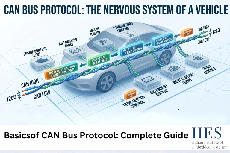
Real-world Example:
In a car:
- The engine control unit sends speed data
- The dashboard reads and displays it
- The ABS system uses it for braking decisions
This is a perfect controller area network example.

CAN vs Other Communication Protocols
To better understand the value of the CAN bus protocol, it helps to compare it with other commonly used communication protocols in embedded systems. Each protocol has its own strengths, depending on the application, speed, and complexity requirements.
Protocol | Speed | Complexity | Use Case |
CAN | Medium | Low | Automotive, industrial systems |
UART | Low | Very Low | Simple device communication |
SPI | High | Medium | High-speed sensors and peripherals |
I2C | Medium | Low | Embedded systems, IC communication |
Key Takeaways:
- CAN protocol is best for multi-device communication with high reliability
- UART is simple but not suitable for complex networks
- SPI offers high speed but requires more wiring
- I2C is efficient for short-distance communication between components
This comparison clearly shows why the controller area network (CAN bus) is widely used in systems where reliability and real-time communication are critical.
Standard CAN and Extended CAN Bit Fields
The CAN message frame defines how data is structured.
Standard CAN Frame (11-bit ID)
Includes:
- Start of Frame (SOF)
- Identifier
- RTR (Remote Transmission Request)
- Data Length Code (DLC)
- Data field
- CRC
- ACK
- End of Frame
Extended CAN Frame (29-bit ID)
Adds:
- Extended Identifier (EID)
This allows more unique message identifiers, which is useful in large-scale systems.
CAN Transceiver: Definition and Function
The CAN transceiver acts as a bridge between the CAN controller and the physical bus.
CAN transceiver function:
- Converts digital signals to differential signals
- Enables noise-resistant communication
- Protects the network from electrical faults
CAN transceiver selection factors:
- Voltage compatibility
- Data rate requirements
- Protection features (ESD, short-circuit)
- Operating environment
Choosing the right CAN transceiver is critical for system stability.
CAN Network Architecture
The CAN network architecture follows a bus topology.
Key characteristics:
- Two-wire differential system
- Termination resistors at both ends
- All nodes share the same communication line
Advantages:
- Reduced wiring
- High reliability
- Easy scalability
CAN Bus Troubleshooting
Even though CAN is reliable, issues can still occur.
Common CAN bus errors:
- Bus-off condition
- Bit errors
- CRC errors
- Acknowledgment errors
Troubleshooting steps:
- Check wiring and connections
- Verify termination resistors (typically 120 ohms)
- Analyze error frames using diagnostic tools
- Inspect transceiver health
These steps are essential for effective CAN bus troubleshooting.
Practical Use Cases of CAN Protocol
1. Automotive Systems
- Engine control
- Airbags
- Infotainment systems
2. Industrial Automation
- PLC communication
- Robotics
3. IoT Applications
- Smart sensors
- Embedded monitoring systems
Mini Case Study:
A modern car can have over 70 ECUs communicating via CAN, reducing wiring weight by up to 30%.
Future Trends in CAN Protocol (2026 and Beyond)
1. CAN FD Adoption
Increasing use in high-speed applications.
2. CAN XL
Next-generation protocol supporting even higher bandwidth.
3. Integration with IoT
CAN is being integrated with cloud and edge systems.
4. Cybersecurity Enhancements
As vehicles become connected, securing CAN networks is critical.
Best Practices for Working with CAN Bus
Do:
- Use proper termination
- Maintain cable quality
- Follow standard protocols
- Monitor error counters
Avoid:
- Incorrect wiring
- Mixing incompatible transceivers
- Ignoring error frames
Common Mistakes to Avoid
- Overloading the bus with unnecessary messages
- Using incorrect baud rates
- Poor grounding
- Ignoring EMI (electromagnetic interference)

Conclusion
The CAN bus protocol remains one of the most reliable and efficient communication systems in embedded technology. From understanding what is CAN protocol and how it works to mastering troubleshooting and architecture, this guide provides a strong foundation.
As industries move toward smarter, connected systems, mastering the controller area network protocol is not just useful, it’s essential.
Whether you’re working on automotive systems, IoT devices, or industrial automation, a solid grasp of CAN will significantly enhance your capabilities.