fbpx

A Comprehensive Guide to the Basics of CAN Bus Protocol - Controller Area Network

A Comprehensive Guide to the Basics of CAN Bus Protocol - Controller Area Network

Introduction

Networking and communication play a crucial role in today’s interconnected world. One key protocol used in these embedded systems is the Controller Area Network (CAN). 

To gain a comprehensive understanding of the CAN bus protocol, this guide will also explore the bit fields used in standard CAN and extended CAN frames, discussing their purpose and significance. Additionally, we will delve into the features and selection criteria for CAN transceivers, as well as explore common errors that can occur in a CAN bus network and the various error-handling mechanisms provided by the CAN protocol.

By grasping the fundamentals and intricacies of the CAN bus protocol through this comprehensive guide, you will be equipped with the knowledge and understanding to work confidently in the realm of networking and communication systems, contributing to the advancement of this vital field.

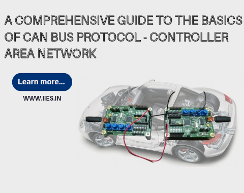
What is the Area Network Controller on the CAN System?

The Area Network Controller, also known as CAN controller, is the core component of the CAN system. It is responsible for managing the data transmission and reception between various nodes connected to the CAN bus. The CAN controller handles the control and scheduling of messages, error detection, and synchronization.

What are CAN Bus Protocols?

CAN bus protocols are a set of rules and standards that define how data is transmitted and received over the CAN bus. The CAN 2.0A and CAN 2.0B protocols are the most common, providing support for standard and extended frames. In recent years, CAN FD (Flexible Data Rate) has been introduced, which allows for higher data rates and increased flexibility.

Basic Principle of CAN Protocol

The CAN protocol is based on a few fundamental principles. Arbitration is one of the key principles, which determines which node can transmit their data over the bus when multiple nodes want to send messages simultaneously. Bit stuffing is another important concept where additional bits are added to ensure data integrity during transmission. The frame structure defines the format of the CAN message, including the identifier, data, and control bits. Error detection mechanisms, such as CRC (Cyclic Redundancy Check), are utilized to detect and correct errors.

How Does a CAN Bus Network Work?

A CAN bus network consists of multiple nodes connected to a common bus. Each node acts as both a receiver and a transmitter, allowing for bidirectional communication. Messages are transmitted serially over the bus and received by all nodes, but only the intended recipient processes the message based on its identifier. Bus arbitration resolves conflicts between nodes that want to transmit simultaneously, ensuring smooth data flow. Synchronization of nodes is critical to maintain proper timing and ensure accurate data transmission.

Standard CAN and Extended CAN Bit Fields

In a standard CAN frame, there are several essential bit fields. The Start of Frame (SOF) bit denotes the beginning of a CAN message, followed by the identifier bits, data length code (DLC), and the data field. Additional control bits, such as the Remote Transmission Request (RTR) bit, provide further functionality. In the extended CAN frame, an additional field called the Extended Identifier (EID) allows for extended message identifiers, increasing the number of unique message identifiers.

CAN Transceiver Features and Transceiver Selection Guide

CAN transceivers play a crucial role in connecting the CAN controller to the physical CAN bus. Transceivers ensure the efficient and reliable transmission of data over the bus. When selecting a transceiver, factors such as voltage levels, speed requirements, and protection features need to be considered. The transceiver should be compatible with the specific CAN protocol being used and should meet the system’s requirements.

CAN Error Handling

In a CAN bus network, errors can occur due to various reasons, such as bus-off conditions, faulty transceivers, or wiring issues. The CAN protocol provides error detection and error handling mechanisms to ensure data integrity. Node error counters, error frames, and error flags are used to detect and handle errors. When troubleshooting common CAN bus errors, steps such as checking the bus wiring, terminating resistors, and analyzing error frames can be helpful.

Conclusion

Understanding the basics of the CAN bus protocol is essential for anyone working with networking and communication systems. In this guide, we explored the role of the CAN controller, different CAN bus protocols, the principles underlying the CAN protocol, the functioning of a CAN bus network, bit fields in standard and extended CAN frames, transceiver selection, and error handling. By grasping these fundamentals, you will be well-equipped to work with CAN bus networks and contribute to the field of networking and communication.