Why Is a Structured Embedded System Design Process Important?
Many embedded projects fail because teams rush directly into coding without proper planning. Professional organizations follow a clearly defined embedded system design lifecycle because it helps deliver reliable, efficient, and cost-effective products.
- Reduce development costs
- Improve product reliability
- Detect design issues early
- Simplify testing and debugging
- Minimize hardware redesign
- Ensure software scalability
- Improve power efficiency
- Meet industry safety standards
- Accelerate product release
For industries such as automotive, aerospace, healthcare, and industrial automation,
a disciplined embedded systems development process is essential for ensuring
product quality, regulatory compliance, and long-term reliability.
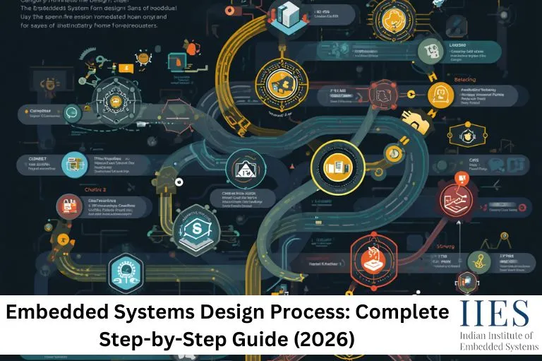
Major Phases of the Embedded Systems Design Lifecycle
A typical embedded systems development process consists of the following phases:
- Requirement Analysis
- System Specification
- Hardware Design
- Software/Firmware Design
- Prototype Development
- System Integration
- Testing and Validation
- Optimization
- Deployment
- Maintenance and Updates
Let’s explore each stage in detail.

Step 1: Requirement Analysis
Every successful embedded project begins by understanding what the system is expected
to accomplish.
During this phase, engineers gather:
- Functional requirements
- Performance expectations
- Power constraints
- Cost limitations
- Environmental conditions
- User requirements
- Safety standards
- Communication interfaces
- Memory requirements
Example
Suppose you’re designing a smart irrigation controller.
The requirements may include:
- Read soil moisture every minute
- Control water pumps automatically
- Send sensor data over Wi-Fi
- Operate for six months on battery power
- Work reliably in outdoor weather conditions
Clearly defining requirements at the beginning helps prevent costly redesigns,
reduces project risks, and ensures the final product meets customer expectations.
Step 2: System Specification
Once the requirements are finalized, engineers convert them into detailed
technical specifications that serve as the blueprint for the entire project.
This specification document typically defines:
- Processor type
- RAM requirements
- Flash memory size
- Clock frequency
- Sensor interfaces
- Communication protocols
- Operating voltage
- Power consumption
- Security features
- Response time
These specifications guide both the hardware and firmware development teams,
ensuring the embedded system is designed according to project requirements.
Step 3: Selecting the Right Microcontroller
Choosing the correct microcontroller is one of the most important decisions in the
embedded system architecture design process. The selected MCU directly
impacts the system’s performance, power efficiency, scalability, and overall cost.
Engineers evaluate several factors before making a decision.
Processing Power
Applications involving AI inference, machine vision, or digital signal processing
require significantly more processing capability than simple sensor monitoring or
control systems.
Memory Capacity
Engineers consider the availability of:
- Flash Memory
- SRAM
- EEPROM
- External memory support
Power Consumption
Battery-powered embedded devices prioritize ultra-low-power microcontrollers such as
ARM Cortex-M0+ or MSP430 to maximize battery life and reduce energy consumption.
Peripheral Availability
The selected microcontroller should provide the required communication interfaces and peripherals, including:
Cost
The chosen microcontroller should satisfy all technical requirements while remaining
within the project’s budget. Selecting an MCU with unnecessary features may increase
development costs without providing additional value.
Step 4: Hardware Design
Once the microcontroller is selected, hardware engineers begin designing the electronic
circuit that forms the foundation of the embedded system. A well-designed hardware
architecture ensures reliability, efficiency, and long-term product stability.
Typical hardware components include:
- Microcontroller (MCU)
- Power supply
- Voltage regulators
- Sensors
- Actuators
- Oscillators
- Communication modules
- Protection circuits
- Memory chips
- Connectors
Hardware engineers also create:
- Circuit diagrams (Schematics)
- PCB layouts
- Power distribution networks
- Signal routing
- EMI/EMC protection
- Thermal management solutions
A well-designed Printed Circuit Board (PCB) improves system stability, minimizes
electrical noise, reduces manufacturing defects, and enhances overall product
performance.
Hardware–Software Co-Design
Modern embedded products rarely develop hardware and firmware independently.
Instead, both teams collaborate throughout the development process to reduce
integration issues and accelerate product development.
Hardware Team Responsibilities
- Finalize PCB design
- Select sensors and electronic components
- Design communication buses
- Validate power circuitry
- Optimize hardware performance
Firmware Team Responsibilities
- Develop device drivers
- Test hardware peripherals
- Create communication protocols
- Optimize memory utilization
- Implement application logic
This parallel development approach shortens development time, improves compatibility
between hardware and software, and reduces costly redesigns during later stages of
the embedded system design lifecycle.
Step 5: Firmware Design
Firmware acts as the intelligence behind an embedded device. It controls hardware,
processes sensor data, manages communication, and executes application-specific
functions in real time.
Firmware developers typically build:
- Bootloader
- Device drivers
- Sensor interfaces
- Communication stack
- Interrupt handlers
- RTOS tasks
- Application logic
- Power management routines
- Error handling modules
Programming Languages
Firmware is commonly developed using:
Popular Embedded Development IDEs
- STM32CubeIDE
- Keil MDK
- MPLAB X IDE
- Code Composer Studio
- Arduino IDE
- PlatformIO
Writing efficient firmware is essential because embedded devices often operate with
limited memory, processing power, and energy resources.
Choosing Between Bare Metal and RTOS
One of the most important architectural decisions in the
embedded systems development process is choosing between a
Bare Metal application and a Real-Time Operating System (RTOS).
Bare Metal Programming
Suitable for applications that require simple control logic and minimal resources.
Best suited for:
- Simple applications
- Low-cost embedded products
- Minimal memory usage
- Fast execution
Examples:
- LED controller
- Temperature monitoring system
- Basic sensor node
RTOS-Based Design
A Real-Time Operating System is ideal for applications that require multiple tasks
to run simultaneously while meeting strict timing requirements.
Suitable for:
- Multiple simultaneous tasks
- Industrial automation
- Automotive electronics
- Medical equipment
- IoT gateways
Popular RTOS Options
An RTOS simplifies task scheduling, synchronization, inter-task communication, and
real-time responsiveness, making it the preferred choice for complex embedded
applications.
Step 6: Prototype Development
After completing the hardware and firmware design, engineers develop a working
prototype to validate the product before mass production. A prototype helps verify
that the system functions as expected and identifies potential issues early in the
embedded systems design process.
The prototype stage focuses on:
- Validating the hardware design
- Verifying firmware functionality
- Testing hardware-software interaction
- Identifying design flaws
- Reducing manufacturing risks
Typical Prototype Activities
- PCB fabrication
- Component assembly
- Firmware flashing
- Sensor calibration
- Power consumption measurement
- Communication testing
- Initial functional verification
Example
Suppose you’re developing a smart home automation system. A typical prototype may
include:
- ESP32 microcontroller
- Temperature and humidity sensor
- Relay module
- Wi-Fi communication
- Mobile application interface
Testing this prototype helps engineers identify hardware defects, firmware bugs,
and communication issues before the product enters mass production, significantly
reducing redesign costs.
Step 7: System Integration
System integration combines every hardware and software module into a fully
functional embedded product. This phase verifies that all individual components
operate together seamlessly.
During integration, engineers combine:
- Device drivers
- Application firmware
- Communication protocols
- Sensors
- Displays
- Actuators
- Wireless communication modules
- Cloud connectivity for IoT devices
The objective is to ensure that every subsystem communicates correctly while
maintaining expected performance and reliability.
Common Integration Challenges
- Communication failures
- Timing conflicts
- Memory overflows
- Power instability
- Driver incompatibility
- Interrupt conflicts
Careful planning and systematic integration reduce debugging time and improve
overall system stability.
Step 8: Testing and Validation
Testing is one of the most critical stages of the
embedded system development lifecycle. It ensures that the
embedded system performs reliably under both normal and extreme operating
conditions.
Functional Testing
Functional testing verifies that every feature works according to the design
specifications.
Examples include:
- Sensor data acquisition
- Motor control
- Display updates
- User input handling
Unit Testing
Individual firmware modules are tested independently before full system
integration.
Typical examples include:
- UART driver
- SPI driver
- ADC module
- Timer module
Unit testing simplifies debugging by isolating software defects during the
early stages of development.
Integration Testing
Integration testing verifies that multiple modules function correctly when
combined into one system.
For example:
- Sensor communicates correctly with the microcontroller.
- Firmware processes sensor data accurately.
- Display updates correctly based on processed information.
Stress Testing
Stress testing evaluates how the embedded system performs under extreme
operating conditions.
Examples include:
- High CPU utilization
- Maximum communication traffic
- Continuous operation for several days
- Peak memory utilization
Stress testing helps uncover hidden performance bottlenecks and stability issues
before deployment.
Environmental Testing
Many embedded systems operate in harsh environments. Environmental testing ensures
that products continue functioning reliably under challenging conditions.
Engineers typically test devices under:
- High temperatures
- Low temperatures
- Humidity
- Dust exposure
- Mechanical vibration
- Electromagnetic Interference (EMI)
- Power fluctuations
Industries such as automotive, aerospace, healthcare, and industrial automation
perform rigorous environmental testing to ensure safety, compliance, and long-term
product reliability.
Step 9: Performance Optimization
Once the embedded system functions correctly, engineers optimize it to improve
performance, reduce power consumption, and maximize reliability. Optimization is
an essential stage of the embedded systems design process because
it directly impacts product efficiency, responsiveness, and user experience.
Memory Optimization
Embedded devices typically have limited RAM and Flash memory. Efficient memory
management helps improve system stability and prevents runtime failures.
Common optimization techniques include:
- Removing unused code and libraries
- Using efficient data structures
- Optimizing stack allocation
- Reducing global variable usage
- Compressing lookup tables where appropriate
Power Optimization
Power efficiency is especially important for battery-operated embedded devices
such as wearable electronics, IoT sensors, and portable medical equipment.
Engineers commonly use the following techniques:
- Sleep modes
- Dynamic clock scaling
- Peripheral shutdown when idle
- Interrupt-driven execution
- Efficient sensor sampling strategies
CPU Optimization
Improving processor efficiency enables faster execution while reducing energy
consumption.
- Optimize algorithms
- Reduce unnecessary polling
- Use DMA for high-speed data transfer
- Minimize interrupt latency
- Optimize RTOS task scheduling
Firmware Optimization
Firmware optimization focuses on improving responsiveness and long-term system
stability.
Typical improvements include:
- Faster boot time
- Reduced response latency
- Better memory management
- Improved communication reliability
- Enhanced fault recovery mechanisms
These optimizations improve overall system performance while extending battery
life and increasing product reliability.

Step 10: Deployment and Manufacturing
After successful testing and validation, the embedded product moves into the
manufacturing phase. Every hardware unit undergoes quality checks before being
delivered to customers.
Deployment activities typically include:
- Final PCB production
- Firmware programming
- Functional testing
- Factory calibration
- Product labeling
- Packaging
- Technical documentation
- Quality assurance inspection
Manufacturers often use automated production testing to verify every device
before shipment, ensuring consistent quality and reducing field failures.
Maintenance and Firmware Updates
The embedded systems development lifecycle continues even after
deployment. Regular maintenance keeps products secure, reliable, and compatible
with evolving technologies.
Common maintenance activities include:
- Bug fixes
- Security patches
- Feature enhancements
- Performance improvements
- Firmware updates
- Hardware revisions
Modern IoT devices frequently support Over-the-Air (OTA) firmware
updates, allowing manufacturers to deploy improvements remotely without requiring
physical access to the device.
Common Challenges in Embedded System Design
Even experienced engineers encounter challenges throughout the
embedded system design lifecycle. Identifying these issues early
helps reduce project risks and development delays.
- Limited memory resources
- Strict power constraints
- Real-time performance requirements
- Hardware-software synchronization
- Electromagnetic interference (EMI)
- Debugging complex firmware
- Cost optimization
- Component availability
- Thermal management
- Cybersecurity vulnerabilities
Addressing these challenges during the design phase improves product quality,
reduces maintenance costs, and shortens development time.
Best Practices for Embedded Systems Design
Professional embedded engineers follow proven development practices to build
high-quality, scalable, and maintainable products.
- Clearly define system requirements before development.
- Select hardware that balances performance, power consumption, and cost.
- Develop hardware and firmware concurrently.
- Write modular and reusable Embedded C code.
- Use version control systems such as Git.
- Perform regular code reviews.
- Test each software module independently before integration.
- Optimize memory and power usage throughout development.
- Document hardware schematics and firmware thoroughly.
- Design with future scalability and firmware updates in mind.
Following these best practices results in more reliable embedded products,
faster development cycles, and lower long-term maintenance costs.
Popular Tools Used in Embedded System Design
Professional embedded engineers use specialized software and hardware tools
throughout the embedded systems design process. These tools
simplify circuit design, firmware development, debugging, testing, and project
collaboration.
Hardware Design Tools
- KiCad
- Altium Designer
- Autodesk Eagle
- OrCAD
These Electronic Design Automation (EDA) tools are used to create circuit
schematics, PCB layouts, component libraries, and manufacturing files.
Firmware Development Tools
- STM32CubeIDE
- Keil MDK
- MPLAB X IDE
- Code Composer Studio
- PlatformIO
These Integrated Development Environments (IDEs) provide code editing,
compilation, debugging, and firmware programming capabilities for various
microcontroller families.
Debugging Tools
- JTAG Debugger
- SWD Debugger
- Logic Analyzer
- Oscilloscope
- Digital Multimeter
Debugging tools help engineers monitor signals, identify firmware bugs,
analyze communication protocols, and verify hardware functionality.
Version Control Systems
Version control systems allow multiple developers to collaborate efficiently,
track code changes, manage releases, and maintain project history throughout
the development lifecycle.
Real-World Applications of the Embedded Systems Design Process
The principles of the embedded systems design process are
applied across numerous industries where reliability, real-time performance,
and energy efficiency are critical.
Automotive Industry
Modern vehicles rely heavily on embedded systems for safety, performance, and
comfort features.
- Engine Control Units (ECUs)
- Advanced Driver Assistance Systems (ADAS)
- Infotainment systems
- Airbag controllers
- Battery Management Systems (BMS)
Healthcare and Medical Devices
Embedded systems enable accurate monitoring, diagnosis, and treatment in
medical equipment.
- Patient monitoring systems
- Infusion pumps
- Wearable health trackers
- ECG machines
- Portable diagnostic devices
Industrial Automation
Factories use embedded controllers to automate manufacturing processes,
increase productivity, and improve operational safety.
- Programmable Logic Controllers (PLCs)
- Industrial robots
- Smart sensors
- Factory automation systems
- Motor control units
Consumer Electronics
Embedded systems power many everyday electronic products.
- Smart TVs
- Washing machines
- Digital cameras
- Gaming consoles
- Smart speakers
Internet of Things (IoT)
IoT devices combine embedded hardware with cloud connectivity to create
intelligent connected products.
- Smart thermostats
- Connected lighting systems
- Home security devices
- Environmental monitoring systems
- Smart agriculture solutions
Aerospace and Defense
Mission-critical aerospace applications demand highly reliable embedded
systems capable of operating in extreme environments.
- Flight control systems
- Navigation equipment
- Communication systems
- Radar systems
- Satellite electronics
These real-world applications demonstrate how a structured development process
helps engineers build reliable, scalable, and safety-critical embedded
products.
Key Takeaways
- The embedded systems design process provides a structured framework for developing reliable hardware and firmware.
- Each stage—from requirement analysis to deployment and maintenance—plays an important role in delivering a successful embedded product.
- Following industry best practices, optimizing performance, and performing comprehensive testing help engineers build scalable, secure, and high-quality embedded systems.
Conclusion
The embedded systems design process is the foundation of successful embedded product development. Whether you’re designing an IoT
sensor, automotive controller, industrial automation system, or medical device, following a structured development lifecycle reduces risks, improves product quality, and accelerates time to market. By combining robust hardware design, efficient firmware development, comprehensive testing, continuous optimization, and regular maintenance, engineers can build embedded systems that meet demanding performance, reliability, and safety requirements. As technologies such as Edge AI, Industry 4.0, and the Internet of Things continue to evolve, mastering the embedded system design lifecycle will remain an essential skill for every embedded systems engineer.