Introduction to the Lua Programming Language
The ESP8266 NodeMCU is a versatile platform for IoT development, and it supports multiple programming languages. One of the primary languages used with NodeMCU is Lua, a lightweight, high-level scripting language. Lua is known for its simplicity and ease of use, making it a great choice for beginners and experienced programmers alike.
Here are some key characteristics of Lua that make it a popular choice for programming NodeMCU:
- Lightweight: Lua is designed to be lightweight and efficient. It doesn’t consume excessive memory or processing power, making it suitable for resource-constrained devices like the NodeMCU.
- High-Level: Lua is a high-level language, which means it provides a more abstract and human-readable syntax compared to low-level languages like C or Assembly.
- Embeddable: Lua is often used as an embedded scripting language in various applications and platforms. In the case of NodeMCU, it’s embedded as a scripting language for IoT development.
- Interpreted: Lua is an interpreted language, meaning that you write your code, and it’s executed by the Lua interpreter. This allows you to make changes to your code and see the results without the need for compilation.
- Community Support: Lua has an active and supportive community, with a wealth of resources and libraries available for various applications.
To get started with Lua programming for NodeMCU, you’ll need to become familiar with its syntax and the specific libraries and functions provided for working with the ESP8266 hardware. Fortunately, there are ample resources available, including official documentation and community-contributed guides and tutorials.
Writing and Uploading Your First “Hello, World!” Program
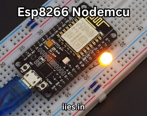
Let’s take the first steps into programming your ESP8266 NodeMCU with Lua by creating a classic “Hello, World!” program. This program will make the onboard LED blink, which is a common introductory task for microcontroller programming.
Here’s the code for a simple “Hello, World!” write a Lua program for the ESP8266 NodeMCU:
“`lua
— Define the pin for the onboard LED (NodeMCU 1.0 has the LED on pin D4)
local ledPin = 4
— Initialize the LED pin as an output
pin.mode(ledPin, gpio.OUTPUT)
— Create a function to toggle the LED state
local function toggled()
if gpio.read(ledPin) == 0 then
gpio.write(ledPin, gpio.HIGH)
else
gpio.write(ledPin, gpio.LOW)
end
end
— Set up a timer to toggle the LED every 1000 milliseconds (1 second)
tmr.alarm(0, 1000, tmr.ALARM_AUTO, toggled)
“`
This code does the following:
- It defines the GPIO pin connected to the onboard LED (D4 in the case of NodeMCU 1.0).
- It initializes the LED pin as an output.
- It creates a function, `toggled`, to toggle the state of the LED between on and off.
- It sets up a timer to execute the `toggled` function every 1000 milliseconds (1 second).
To upload this program to your NodeMCU, follow these steps:
- Start your computer’s Arduino IDE program.
- Copy the Lua code above and paste it into the code editor.
- Save your program with a meaningful name.
- Click the “Upload” button (the right-pointing arrow) in the Arduino IDE to compile and upload the code to your NodeMCU.
- Observe the onboard LED on your NodeMCU board. It should start blinking every second, and you’ve successfully programmed your ESP8266 NodeMCU with Lua.
This “Hello, World!” program serves as a foundation for more complex projects. You can now build upon this knowledge to create a wide range of IoT applications and experiments. In the next subsection, we’ll explore some basic coding examples to further understand NodeMCU’s capabilities.
Basic Coding Examples to Understand NodeMCU’s Capabilities
The ESP8266 NodeMCU is a versatile platform with various capabilities beyond blinking an LED. To help you grasp its potential, let’s explore a few basic coding examples that demonstrate some common IoT tasks.
- Reading a Sensor (DHT22 Temperature and Humidity Sensor)
One of the fundamental tasks in IoT is reading data from sensors. In this example, we’ll use the popular DHT22 sensor to measure temperature and humidity. You’ll need to connect the sensor to your NodeMCU and install the necessary libraries.
“`lua
— Include the DHT library
dht = require(“DHT”)
— Define the pin to which the DHT sensor is connected (DHT22 data pin)
local dating = 2
— Use the DHT sensor to read the temperature and humidity.
status,
temp, humid, temp_dec, humi_dec = dht.read(dating)
if status == dht.OK then
print(“Temperature: ” .. temp .. “°C”)
print(“Humidity: ” .. humi .. “%”)
elseif status == dht.ERROR_CHECKSUM then
print(“DHT Checksum error.”)
elseif status == dht.ERROR_TIMEOUT then
print(“DHT Timeout error.”)
else
print(“DHT Unknown error.”)
end
“`
In this code:
– We include the DHT library for NodeMCU, which simplifies communication with the DHT22 sensor.
– We define the pin to which the DHT22 sensor’s data pin is connected (in this example, it’s GPIO pin 2).
– We read temperature and humidity data from the DHT22 sensor, handling different error conditions and printing the results.
This example demonstrates how to interface with sensors and read data, which is a common requirement in IoT applications.
- Controlling an Actuator (Servo Motor)
IoT applications often involve controlling actuators like servo motors. In this example, we’ll control a servo motor using the NodeMCU. You’ll need to connect the servo motor to your NodeMCU and install the necessary libraries.
“`lua
— Include the Servo library
servo = require(“servo”)
— Specify which pin the servo motor is attached to.
local servoPin = 1
— Create a servo instance
myServo = servo.attach(serving)
— Position the servo at a particular angle.
my servo.write(90) — 90 degrees
“`
In this code:
– We include the Servo library for NodeMCU, which facilitates servo motor control.
– We define the pin to which the servo motor is connected (in this example, it’s GPIO pin 1).
– We create a servo instance and attach it to the specified pin.
– We move the servo motor to a specific angle (in this case, 90 degrees).
This example illustrates how to control actuators like servo motors, opening the door to a wide range of physical interactions in your IoT projects.
- Connecting to Wi-Fi
One of the defining features of the NodeMCU is its built-in Wi-Fi connectivity. This allows your IoT device to connect to the internet, communicate with cloud services, and interact with other devices. Here’s a basic example of connecting your NodeMCU to a Wi-Fi network:
“`lua
— Set up Wi-Fi credentials
local ssid = “YourWiFiSSID”
local password = “YourWiFiPassword”
— Connect to the Wi-Fi network
wifi.set mode(wifi. STATION)
wifi. sta.config(ssid, password)
— Wait for a connection
tmr.alarm(0, 1000, tmr.ALARM_AUTO, function()
if wifi. sta.get() == nil then
print(“Connecting to Wi-Fi…”)
else
tmr.stop(0) — Stop the timer
print(“Connected to Wi-Fi”)
print(“IP Address: ” .. wifi.sta.get())
end
end)
“`
In this code:
– We set up the Wi-Fi credentials (replace “YourWiFiSSID” and “YourWiFiPassword” with your network’s SSID and password).
– We configure the NodeMCU to connect to the Wi-Fi network in station mode.
– We use a timer to check if the NodeMCU has successfully obtained an IP address. Once connected, it prints the IP address.
This example showcases the Wi-Fi capabilities of the NodeMCU and its ability to connect to your local network.
These coding examples provide a glimpse of what you can achieve with the ESP8266 NodeMCU and the Lua programming language. With this foundation, you can begin building more complex IoT applications, from environmental monitoring systems to smart home devices. In the next section, we’ll explore how to connect your NodeMCU to Wi-Fi networks.
Connecting to Wi-Fi Networks
Configuring Wi-Fi Credentials
One of the defining features of the ESP8266 NodeMCU is its built-in Wi-Fi connectivity. To unlock its potential, the first step is to configure your NodeMCU to connect to your local Wi-Fi network. This allows your NodeMCU to communicate with the internet, send and receive data, and interact with other IoT devices. Here’s how you can set up your NodeMCU to connect to a Wi-Fi network:
- Start your computer’s Arduino IDE program.
- Create a new sketch (File > New) or open an existing one.
- In your sketch, you need to provide your Wi-Fi network credentials. Use the following code template and replace `”Your_SSID”` and `”Your_Password”` with your network’s SSID (the name of your Wi-Fi network) and the network password, respectively:
“`cpp
const char* ssid = “Your_SSID”;
const char* password = “Your_Password”;
“`
- Now, let’s add the code to connect to Wi-Fi. Add the following code to your sketch, typically in the `setup()` function:
“`cpp
// Connect to Wi-Fi
WiFi.begin(ssid, password);
// Wait for the connection to complete
while (WiFi.status() != WL_CONNECTED) {
delay(1000);
Serial.println(“Connecting to WiFi…”);
}
// Connected to Wi-Fi
Serial.println(“Connected to Wi-Fi”);
“`
Here’s what the code does:
– It uses `WiFi.begin(ssid, password)` to initiate the connection to your Wi-Fi network.
– The `while` loop checks the connection status using `WiFi.status()`. It repeatedly prints “Connecting to WiFi…” and waits for a successful connection.
– Once the NodeMCU successfully connects to your Wi-Fi network, it prints “Connected to Wi-Fi.”
This setup allows your NodeMCU to join your Wi-Fi network. Make sure to upload this code to your NodeMCU by clicking the “Upload” button in the Arduino IDE.
How to Connect NodeMCU to a Wi-Fi Network
To connect your NodeMCU to a Wi-Fi network, follow these steps:
- Power your NodeMCU by connecting it to your computer via a micro-USB cable.
- Start your computer’s Arduino IDE program.
- Load the sketch you created or modified in the previous section, which includes your Wi-Fi credentials and the connection code.
- Select your NodeMCU board from the “Tools” menu. Go to “Tools” > “Board” and choose “NodeMCU 1.0 (ESP-12E Module).”
- Select the COM port to which your NodeMCU is connected in the “Tools” > “Port” menu. The correct COM port should be labeled as “USB-SERIAL CH340” (or something similar).
- Click the “Upload” button (the right-pointing arrow) to compile and upload the code to your NodeMCU.
- Open the Arduino IDE’s serial monitor by clicking the magnifying glass icon in the upper-right corner of the window. Set the baud rate to 115200.
- Observe the serial monitor for messages. If everything is configured correctly and your Wi-Fi network is available, you should see a message indicating that the NodeMCU is connecting to Wi-Fi and, eventually, that it’s “Connected to Wi-Fi.”
Once you see the “Connected to Wi-Fi” message, your NodeMCU is successfully connected to your Wi-Fi network. It can now send and receive data over the internet and communicate with other devices on your network. You’re ready to start building IoT applications that leverage this Wi-Fi connectivity.
Troubleshooting Wi-Fi Connectivity Issues
Sometimes, Wi-Fi connectivity issues may arise when working with the NodeMCU. Here are some common troubleshooting steps to address these issues:
- Double-check Wi-Fi Credentials: Ensure that you have entered the correct SSID and password in your code. Even a single character discrepancy can prevent the NodeMCU from connecting to the network.
- Wi-Fi Network Availability: Make sure that your Wi-Fi network is available and within range of your NodeMCU. Check for any issues with your Wi-Fi router or network configuration.
- Signal Strength: The NodeMCU’s Wi-Fi antenna may not be as powerful as that of a typical Wi-Fi router. If your NodeMCU is located far from the router, consider moving it closer to improve signal strength.
- SSID Visibility: Some Wi-Fi networks may hide their SSID (network name) for security reasons. If your network is hidden, you’ll need to modify your code to connect to a hidden network or make the SSID visible.
- Network Security: Ensure that your network’s security protocol (e.g., WPA2, WPA3) matches the one specified in your code. If your network uses a different security protocol, you’ll need to adjust the code accordingly.
- Firewalls and Router Settings: Firewalls or specific router settings may block the NodeMCU’s communication. Check your router settings to ensure that the NodeMCU’s connection is not being blocked.
- Serial Monitor Debugging: Use the serial monitor in the Arduino IDE to view debugging information. It can provide insights into any errors or issues during the Wi-Fi connection process.
- Firmware Update: Ensure that you have the latest firmware installed on your NodeMCU. Firmware updates may include improvements related to Wi-Fi connectivity.
- Power Supply: Inadequate power supply can affect Wi-Fi connectivity. Make sure your NodeMCU is powered sufficiently to avoid potential issues.
- Static IP: Some IoT applications may benefit from assigning a static IP address to the NodeMCU. This can help prevent IP address conflicts and ensure consistent network connectivity.
By following these troubleshooting steps, you can address common Wi-Fi connectivity issues and ensure that your NodeMCU successfully connects to your network, paving the way for a wide range of IoT projects.
Building Smart Devices
Overview of IoT (Internet of Things)
The Internet of Things (IoT) is a transformative technology that’s changing the way we interact with the physical world. It’s a network of connected devices, sensors, and objects that can communicate with each other and with centralized systems via the Internet. Smart cities, smart homes, industrial automation, and healthcare are just a few examples of IoT applications.
Key elements of IoT include:
- Sensors: IoT devices are equipped with various sensors that collect data. These sensors can measure temperature, humidity, motion, light, and more.
- Connectivity: IoT devices are connected to the internet or other devices, allowing them to transmit and receive data.
- Data Processing: IoT devices often include microcontrollers or microprocessors that process data and make decisions.
- Cloud Services: Data from IoT devices is often sent to cloud platforms for storage, analysis, and remote control.
- User Interfaces: IoT applications typically have user interfaces, such as mobile apps or web dashboards, that allow users to interact with the devices and access data.
IoT has the potential to revolutionize various industries, making processes more efficient, improving decision-making, and enhancing convenience and safety in our daily lives.
Examples of Smart Devices You Can Build with NodeMCU
The ESP8266 NodeMCU is an excellent platform for building a wide range of smart devices. Here are a few illustrations to encourage your imagination:
- Smart Thermostat: Create a smart thermostat that allows you to control and monitor the temperature in your home remotely. You can program it to adjust the temperature based on your preferences and schedule.
- Smart Home Automation: Build a system that automates lighting, HVAC, and other appliances in your home. Control them through a mobile app or voice commands.
- Weather Station: Develop a weather station that collects data on temperature, humidity, air pressure, and more. You can display this data on a local screen or send it to a cloud service for analysis.
- Smart Irrigation System: Design an irrigation system for your garden that waters your plants based on soil moisture levels. You can also monitor water usage and receive alerts on your phone.
- Security Camera: Convert your NodeMCU into a security camera. You can stream video to a web application or send alerts when motion is detected.
- Pet Feeder: Create an automated pet feeder that dispenses food at scheduled times. You can control it remotely and even feed your pet from your smartphone.
- Environmental Monitoring: Build a device to monitor air quality, pollution, or radiation levels in your surroundings. This data can be useful for health and safety.
- Smart Door Lock: Develop a smart door lock system that allows you to lock and unlock your door remotely, provide access to guests, and receive alerts when someone enters or exits.
- Water Quality Monitor: Build a water quality monitoring system for your aquarium or a local body of water. Measure parameters like pH, dissolved oxygen, and temperature.
- Wearable Health Tracker: Create a wearable device that tracks your health and fitness data, such as heart rate, steps, and sleep patterns. The data can be sent to a mobile app for analysis.
These are just a few examples of the many smart devices you can build with the ESP8266 NodeMCU. The versatility and connectivity of the NodeMCU make it a powerful tool for bringing your IoT ideas to life.
Step-by-Step Guide to Building a Basic IoT Device
To help you get started with building a basic IoT device using the ESP8266 NodeMCU, we’ll walk through the process of creating a simple weather station that measures temperature and humidity and displays the data on a local OLED display. This project will introduce you to the concepts of sensor integration, data collection, and display output.
Materials Needed:
- ESP8266 NodeMCU board
- DHT22 temperature and humidity sensor
- SSD1306 OLED display (128×64 pixels)
- Breadboard and jumper wires
- Micro-USB cable and power source
Steps:
Step 1: Hardware Connection**
– Connect the DHT22 sensor to your NodeMCU as follows:
– DHT22 VCC to NodeMCU 3.3V
– DHT22 GND to NodeMCU GND
– DHT22 DATA to NodeMCU D2 (you can use a different GPIO pin, but make sure to update the code accordingly)
– Connect the SSD1306 OLED display to your NodeMCU:
– OLED VCC to NodeMCU 3.3V
– OLED GND to NodeMCU GND
– OLED SDA to NodeMCU D1 (SDA)
– OLED SCL to NodeMCU D2 (SCL)
Step 2: Set Up Arduino IDE
– Open the Arduino IDE on your computer.
– Add support for the ESP8266 board: Go to “File” > “Preferences” and add the following URL to the “Additional Boards Manager URLs” field: http://arduino.esp8266.com/stable/package_esp8266com_index.json
– Install the ESP8266 board support: Go to “Tools” > “Board” > “Boards Manager,” search for “esp8266,” and install the package.
Step 3: Install Libraries
– Install the necessary libraries for the DHT22 sensor and SSD1306 OLED display. Go to “Sketch” > “Include Library” > “Manage Libraries,” and search for “Adafruit SSD1306” and “DHT sensor library.” Install these libraries.
Step 4: Write the Code
– Write the Arduino code to read data from the DHT22 sensor and display it on the OLED display. Below is a sample code template to get you started:
“`cpp
#include <Adafruit_SSD1306.h>
#include <DHT.h>
#define SCREEN_WIDTH 128
#define SCREEN_HEIGHT 64
#define OLED_RESET -1
Adafruit_SSD1306 display(SCREEN_WIDTH, SCREEN_HEIGHT, &Wire, OLED_RESET);
#define DHTPIN D2
#define DHTTYPE DHT22
DHT dht(DHTPIN, DHTTYPE);
void setup() {
Serial.begin(115200);
if(!display.begin(SSD1306_I2C_ADDRESS, 4, 5)) {
Serial.println(F(“SSD1306 allocation failed”));
for(;;);
}
display.display();
delay(2000);
display.clearDisplay();
dht.begin();
}
void loop() {
delay(2000);
float temperature = dht.readTemperature();
float humidity = dht.readHumidity();
display.clearDisplay();
display.setTextSize(1);
display.setTextColor(SSD1306_WHITE);
display.setCursor(0,0);
display.print(“Temp: “);
display.print(temperature);
display.print(” C”);
display.setCursor(0,20);
display.print(“Humidity: “);
display.print(humidity);
display.print(” %”);
display.display();
}
“`
Step 5: Upload and Test
– Connect your NodeMCU to your computer using a micro-USB cable.
– Select the correct COM port and NodeMCU board in the Arduino IDE.
– Click the “Upload” button to compile and upload the code to your NodeMCU.
– Open the Arduino IDE’s serial monitor to view debug messages.
– You should see temperature and humidity data displayed on the OLED screen.
This basic project serves as a starting point for more complex IoT applications. You can expand on it by adding features like data logging, internet connectivity, and remote monitoring.
In the following section, we’ll explore how to communicate with cloud services using the ESP8266 NodeMCU.
Communicating with Cloud Services
Introduction to Cloud-Based Services for IoT
One of the key capabilities of IoT devices is their ability to communicate with cloud-based services. Cloud platforms provide a central hub for data storage, analysis, and remote control, allowing you to build sophisticated IoT applications. Here’s an overview of how cloud-based services play a vital role in IoT:
- Data Storage: IoT devices generate vast amounts of data. Cloud platforms can store this data securely and at scale. This data can be historical logs, sensor readings, or user interactions.
- Data Analysis: Cloud services enable you to process and analyze the data generated by your IoT devices. You can gain insights, detect patterns, and make informed decisions based on this data.
- Remote Control: Cloud platforms facilitate remote control of IoT devices. You can send commands to your devices, update their firmware, or modify their behavior from anywhere in the world.
- Scalability: Cloud services offer the ability to scale your IoT applications. Whether you have one device or thousands, the cloud can accommodate your needs.
- Data Visualization: Cloud-based platforms often provide tools for data visualization. You can create dashboards and reports to monitor and present data effectively.
- Security: Cloud platforms typically include security features like authentication, encryption, and access control to protect your IoT data and devices.
Popular cloud platforms for IoT include Amazon Web Services (AWS), Microsoft Azure, Google Cloud Platform (GCP), IBM Cloud, and various IoT-focused platforms like ThingSpeak and Adafruit IO. Each of these platforms offers IoT-specific services, making it easier to develop and deploy IoT applications.
Connecting NodeMCU to Cloud Platforms
To connect your ESP8266 NodeMCU to a cloud platform, you need to follow these general steps:
- Create an Account: Sign up for an account on the cloud platform of your choice. Many platforms offer free tiers with limited resources for experimentation.
- Create a Project: Set up a new project on the cloud platform. This project will house your IoT application and its associated resources.
- Generate Credentials: Obtain the necessary credentials (such as access keys and tokens) from the cloud platform to allow your NodeMCU to interact with it securely.
- Choose Communication Protocol: Decide on the communication protocol to use between your NodeMCU and the cloud platform. Common choices include HTTP, MQTT, and WebSockets.
- Implement Cloud Code: Write code on your NodeMCU that sends data to the cloud platform. This may involve making HTTP requests, publishing messages via MQTT, or using a dedicated library provided by the platform.
- Receive and Process Data: Set up mechanisms to receive data from the cloud. For example, you may want to receive control commands or display data sent from the cloud platform on your NodeMCU.
- Test and Debug: Test your NodeMCU’s connection to the cloud platform. Use debugging tools and logs to identify and resolve any issues.
- Deploy and Scale: Once your IoT application is working as expected, you can deploy it to multiple devices and scale your project up or down based on your requirements.
Data Exchange and Remote Control of NodeMCU Devices
Once your NodeMCU is connected to a cloud platform, you can achieve various capabilities, such as data exchange and remote control. Here’s how it works:
Data Exchange:
– Your NodeMCU collects data from sensors or interacts with its environment.
– This data can include sensor readings (temperature, humidity, etc.), device status, or any other information you want to monitor.
– Your NodeMCU sends this data to the cloud platform using the chosen communication protocol.
– The cloud platform stores, processes, and potentially analyzes the data. You can create rules, set alerts, and visualize the data on dashboards.
– Users or other devices can access this data through web interfaces or applications.
Remote Control:
– The cloud platform allows you to send commands and instructions to your NodeMCU devices.
– You can control actuators, update device settings, or trigger specific actions remotely.
– For example, you can turn on or off a connected appliance, change the temperature settings of a smart thermostat, or lock and unlock a smart door.
Here’s a simplified code snippet for sending data from your NodeMCU to a cloud platform using HTTP requests. Please note that the actual code and implementation may vary depending on the chosen cloud platform and communication protocol:
“`cpp
#include <ESP8266HTTPClient.h>
#include <WiFiClientSecure.h>
const char* serverAddress = “https://your-cloud-api.com”;
const char* apiKey = “your-API-key”;
float temperature = 25.5; // Replace with actual sensor data
void setup() {
// Configure Wi-Fi and join the network
// Make an HTTP POST request to send data to the cloud platform
HTTPClient http;
http.begin(server address);
http.addHeader(“Content-Type”, “application/json”);
String data = “{\”temperature\”:” + String(temperature) + “}”;
int httpResponseCode = http.POST(data);
if (httpResponseCode > 0) {
// Successful POST request
Serial.print(“HTTP Response Code: “);
Serial.println(httpResponseCode);
} else {
// Error handling
Serial.print(“HTTP Error: “);
Serial.println(httpResponseCode);
}
http.end();
}
void loop() {
// Your main program loop
}
“`
This code snippet demonstrates sending temperature data to a cloud platform using an HTTP POST request. Make sure to replace `your-cloud-api.com` and `your-api-key` with the actual cloud platform details. The exact implementation details will depend on the specific cloud platform’s APIs and requirements.
Troubleshooting and Common Issues
As you dive into building IoT projects with the ESP8266 NodeMCU, you may encounter various challenges and issues. Here are some typical issues you could encounter and solutions:
Identifying and Fixing Common Problems
- Wi-Fi Connectivity Issues: If your NodeMCU is unable to connect to Wi-Fi, double-check your SSID and password, ensure your network is within range, and consider other troubleshooting steps mentioned earlier.
- Sensor Readings Are Inaccurate: If your sensor readings (e.g., temperature, humidity) are inaccurate, verify that the sensor is correctly connected to the NodeMCU. You may also need to calibrate or check the datasheet for your specific sensor.
- Data Not Displayed on OLED: If data isn’t displayed on the OLED screen, check the wiring connections and ensure the OLED library is correctly installed. Additionally, review the code to ensure that data is correctly sent to the display.
- Unable to Upload Code: If you’re unable to upload code to the NodeMCU, confirm that the correct COM port and board settings are selected in the Arduino IDE. Restart the NodeMCU, try different USB ports, and ensure that the micro-USB cable is functioning.
- Device Doesn’t Respond to Cloud Commands: If your NodeMCU doesn’t respond to commands from the cloud platform, verify that the cloud platform’s API and integration are correctly set up. Check that the NodeMCU is correctly listening for and processing incoming commands.
- Power Supply Issues: Inadequate or unstable power supply can lead to unpredictable behavior. Ensure that your NodeMCU receives a stable power source within the recommended voltage range.
- Interference and Signal Strength: Wi-Fi signals can be affected by interference from other devices or physical obstacles. Reposition your NodeMCU to minimize interference and improve signal strength.
- Code Errors: Carefully review your code for syntax errors, typos, or logical issues. Use the serial monitor for debugging by adding print statements to your code to trace the program’s flow.
- Resource Constraints: The NodeMCU has limited memory and processing capabilities. Be mindful of resource constraints when developing your projects. Optimize your code, and consider resource-friendly libraries and approaches.
Resources and Communities for Seeking Help
When facing challenges or seeking assistance with NodeMCU and IoT projects, consider these resources:
- Official Documentation: Refer to the official documentation of the ESP8266 NodeMCU, Arduino, and any other libraries you’re using. They often contain valuable information and examples.
- Online Forums: Platforms like the Arduino Forum, Stack Overflow, and Reddit’s r/esp8266 community are great places to ask questions and seek advice from the community.
- GitHub: Check for GitHub repositories and issues related to your specific problem. Many libraries and projects related to the NodeMCU are open-source and have active communities.
- Online Tutorials: There are numerous online tutorials and guides covering a wide range of NodeMCU and IoT topics. Websites like Adafruit, Instructables, and Hackster.io offer a wealth of projects and tutorials.
- YouTube: Video tutorials can provide step-by-step guidance for NodeMCU projects. YouTube channels like “Random Nerd Tutorials” and “Andreas Spiess” focus on ESP8266 and IoT.
- Local IoT and Maker Communities: Check if there are local IoT, maker, or electronics communities in your area. You might find meetups or events where you can get hands-on help.
- Official Support Channels: Some cloud platforms and manufacturers have official support channels or forums where you can get assistance for specific products or services.
- Debugging Tools: Learn how to use debugging tools like the Arduino IDE’s serial monitor to trace issues and understand the behavior of your NodeMCU.
Remember that troubleshooting and problem-solving are integral parts of the learning process. Don’t be discouraged by challenges; instead, use them as opportunities to enhance your skills and gain a deeper understanding of IoT development.
Advanced NodeMCU Projects
As you gain experience with the ESP8266 NodeMCU, you can explore more advanced projects that leverage the NodeMCU’s capabilities. Here are some project ideas to challenge your skills and creativity:
Home Automation System
Create a comprehensive home automation system that allows you to control and monitor various aspects of your home. You can automate lighting, HVAC, security, and entertainment systems. Integrate voice control and develop a mobile app for remote access.
Voice Assistant Integration
Integrate voice assistant services like Amazon Alexa or Google Assistant into your NodeMCU projects. This allows you to control devices and get information through voice commands.
Energy Monitoring System
Build an energy monitoring system that tracks electricity consumption in your home. You can use current sensors and NodeMCU to measure energy usage and visualize the data on a web dashboard. Implement alerts for abnormal consumption patterns.
Smart Garden
Create a smart garden system that monitors soil moisture, temperature, and light levels. Use the data to control irrigation and provide optimal conditions for your plants. Implement a mobile app for remote garden management.
Security and Surveillance
Enhance your home security with advanced features. Develop a smart camera system with motion detection and facial recognition. Integrate it with alarm systems and remote monitoring.
Autonomous Robot
Build an autonomous robot using NodeMCU as the brain. Equip it with sensors for obstacle detection, navigation, and environment monitoring. You can explore indoor mapping and autonomous exploration.
Weather Forecasting
Develop a localized weather forecasting system using sensors for temperature, humidity, pressure, and weather conditions. You can display the forecast on a screen or send alerts for changing weather patterns.
Mobile Health Monitoring
Create wearable health devices using NodeMCU to track vital signs like heart rate, blood pressure, and body temperature. Send the data to a mobile app for real-time health monitoring.
Industrial IoT (IIoT) Applications
Apply NodeMCU in industrial settings for condition monitoring, predictive maintenance, and process optimization. Use sensors and actuators to control machines and monitor equipment health.
Home Brewery Automation
Automate home brewing processes using NodeMCU to control temperature, manage fermentation, and monitor brewing conditions. You can receive brewing notifications and log recipes.
Smart Mirror
Build a smart mirror that displays useful information like time, weather, news, and your daily schedule. Implement voice commands and gestures for interaction.
Drone Control
Use NodeMCU to develop a drone control system. Add features like GPS navigation, live video streaming, and autonomous flight modes.
Data Logger and Analysis
Create a data logging system that collects data from multiple sensors and sends it to the cloud for analysis. This could be used for environmental monitoring, research, or data-driven decision-making.