Preface:
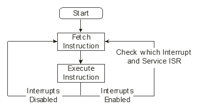
An interrupt is a communication to the processor indicating that an event has occurred. Upon receiving an interrupt signal, a processor executes a designated critical task. A processor can be prompted by this signal to pause its current sequence of instructions and execute an alternative sequence (function) to respond to the signal (Interrupt). An interrupt is detected or sampled by the processor in the last clock cycle, or just before it, of the final machine cycle for every instruction executed.
Interrupt flow control
Signals originating from external sources are classified as Hardware Interrupts, whereas those generated by software applications are termed Software Interrupts.
Interrupts Vs. polling:
Programming for several devices can be accomplished through two techniques: the interrupt method and the polling method.
The interrupt method involves a device sending an interrupt to the microcontroller to request service whenever it needs assistance. Once the signal is received, the microcontroller ceases the current program’s execution and then processes the device using the relevant subroutine which is called ISR.
Utilizing the polling method, the microcontroller perpetually observes the device’s status and initiates the service when the necessary condition is achieved. Polling can oversee the status of several devices and interact with them when particular conditions arise; however, it is not considered an efficient strategy for the microcontroller.
What are the reasons for using interrupts?
Interrupts are viewed as critical or atypical situations that necessitate the processor’s response. Interrupts are employed by external peripheral devices to notify the system of events and to request the performance of certain actions.
Maskable and Non-Maskable Interrupts:
Interrupts generated by a processor are classified into maskable and non-maskable categories. A maskable interrupt refers to an interrupt that can be turned off or disabled by the central processing unit. The CPU is obligated to respond to a Non-Maskable Interrupt (NMI) and cannot overlook it.
Redirecting to the Interrupt Service Routine (ISR)
Upon the occurrence of an interrupt, it is essential to transfer control to the address designated for the Interrupt Service Routine (ISR). Essentially, two approaches can be utilized to achieve this.
- Vectored
- Non-Vectored (Scalar)
Vectored Interrupts:
In the context of vectored interrupts, the hardware allocates a specific address to each individual interrupt. Each time a vectored interrupt takes place, the processor instinctively accesses the Interrupt Service Routine (ISR) that is stored at a designated address.
Non-Vectored (Scalar Interrupt):
In essence, the processor will ask the device responsible for the interrupt to provide the address of the ISR. Following the identification of the ISR address, the program’s control is directed to the appropriate ISR. The performance of scalar interrupts is hindered by the fact that ISR addresses are not easily accessible.
8051 Interrupts
The 8051 features five primary sources of interrupts.
- INT0
- INT1
- Timer0
- Timer1
- Serial Port
The External Interrupts are represented by INT0 and INT1, whereas Timer0, Timer1, and Serial port Interrupts fall under the category of Internal Interrupts.
External Interrupts:
By setting or clearing the IT1 or IT0 bits in the TCON Register, the external source can be programmed to activate based on either level or transition conditions. An external interrupt is initiated by a low level at the INT0/1 pin when IT0/1 equals 0. An edge-triggered external interrupt occurs when IT0/1 equals 1. In this operational mode, if the INT0/1 pin displays a high signal during one cycle and a low signal in the following cycle, the external interrupt flag IE0/1 within the TCON register will be set. At that point, an interruption occurs in the processor.
To ensure proper sampling, the external interrupt pins, which are sampled once during each machine cycle, require that an input signal remains high or low for at least 12 oscillator periods. When dealing with a transition-activated external interrupt, it is necessary for the external source to keep the request pin high for at least one cycle before subsequently holding it low for a minimum of one cycle. This procedure is implemented to confirm that the transition is visible, which will lead to the setting of the interrupt request flags IE0 and IE1. When the service routine is executed, the CPU will automatically clear IE0/1.
In cases where the external interrupt is level-triggered, the external source is required to keep the request active until the interrupt is successfully generated. The request needs to be deactivated before the interrupt service routine finishes, or else a new interrupt will occur.
Timer Interrupts
The generation of interrupts for Timer 0 and Timer 1 occurs when the associated registers, T0 (TH0-TL0) and T1 (TH1-TL1), roll over. When an interrupt occurs, the CPU routes to the service subroutine, and the relevant flag is cleared without manual intervention. The process of serial data communication is generally slow, requiring multiple milliseconds for the transmission of each data byte. To prevent the unnecessary consumption of processor resources, Serial Data flags are integrated into SCON, enhancing the efficiency of data transmission and reception.
In the SCON register, the serial data flags TI and RI are triggered whenever a data byte is sent (TI) or received (RI). By applying a logical OR to these flags, an interrupt is created for the program. It is essential for the ISR program to assess these flags to ascertain the cause of the interrupt and then proceed to clear the flag. Automatic clearing of these flags will not take place; therefore, it is the programmer’s responsibility to clear them within the routines that handle serial data flags, as the microcontroller does not have the capability to ascertain whether the interrupt originated from the TI or RI flag.
SFR’s for Interrupts:
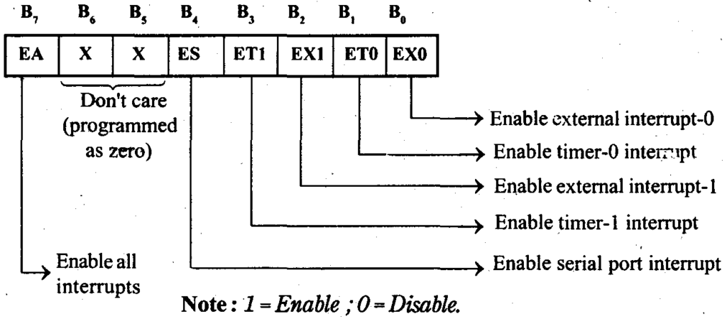
Interrupt Enable (IE) Register:
Individual interrupt sources can be turned on or off by adjusting the corresponding bits in the Special Function Register IE.
Interrupt Priority (IP) Register:
It is possible to individually set each interrupt source to one of two available priority levels. The priority levels for each interrupt can be determined by setting the corresponding bits in the Interrupt Priority Register within the Special Function Register.