A platform for learning and creating embedded systems based on the 8051 microcontroller is the 8051 development board. Its extensive availability, rich instruction set, and ease of use make it a popular microcontroller for embedded applications.
An overview of the topics that could be covered in a document about the 8051 development board is provided below:
- Microcontroller Overview:
Intel created the 8051 microcontroller in 1980. In embedded systems, this 8-bit microcontroller is widely used.
Architecture:
A Memories (ROM AND RAM),I/O ports, timers, Processor and support for serial communication are all part of the 8051 development board.
Features:
- CPU with 8 bits
- On-chip ROM (4KB) (EPROM, Flash)
- RAM of 128 bytes.
- A pair of 16-bit timers
- Four I/O ports in parallel
- For communication, using a protocol like Universal Asynchronous Receiver Transmitter (UART).
- Interrupt the system
- Overview of the 8051 Development Board
The 8051 Development Board: What is it? Users can create, test, and prototype software for the 8051 microcontroller using this hardware platform.
Parts:
Microcontroller: Variants of the core 8051 microcontroller.
The clock signal is produced by a crystal oscillator. Usually, the power supply is 5V DC. Input / Output Ports: External ports used to interface with sensors, switches, LEDs, and other devices.
Programming Interface: The 8051 can be programmed via a serial port or ISP (In-System Programming).
Peripheral Components:
- LCD/LED displays
- Press switches and buttons
- ADC functionality potentiometer (if included),
Sensors for testing input.
- Communication: USB for data transfer or a serial communication module (RS-232).
- Description of Hardware
Microcontroller Pin Configuration:
Each pin’s functions include power, ground, I/O, reset, and so forth.
I/O Ports: An explanation of P0 through P3, the four 8-bit I/O ports.
Timers and Interrupts: An explanation of the two 16-bit timers and how to use them to create time-based events or delays.
Serial Communication: An explanation of the UART module’s functions and usage
The crystal oscillator circuit provides information about the oscillator circuit that generates a consistent clock signal.
- Development of Software Programming
Environment: Assembly/C compilers, MPLAB, Keil uVision, and other IDE/compiler options. Setting up the 8051: An introduction to 8051 assembly language programming. creating basic programs (such as those that read inputs, blink LEDs, etc.).
Debuggingà The process of troubleshooting code using debuggers
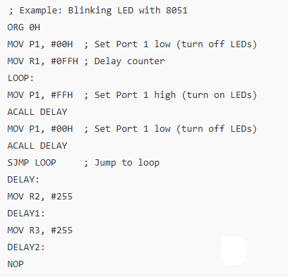
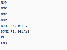
Example of Code: An example of a simple program that toggles an LED on a port that is connected.
An example of serial communication (data transmission and reception via UART)


5. Connecting to the Periphery
- Connecting and controlling LEDs and switches with GPIO pins is known as “interfacing.”
- LCD Display Interface: To display messages, an LCD with 16×2 characters can be interfaced. Interfacing Sensors: temperature sensors, other analog devices, and ADC interfacing (if applicable)
- External Memory: How to interface external EEPROM or RAM with the 8051 if it is utilized.
6. 8051 Development Board Applications
Embedded Systems: Automation projects, robotics, and simple control systems. Home automation is the use of the 8051 to manage lighting, appliances, and other aspects of the house.
Sensor Monitoring: Using a variety of sensors to monitor the environment (temperature, humidity, etc.).
Communication: Using RS-232 or UART to implement wireless communication protocols.
7. Debugging and Troubleshooting
Typical Problems: improper wiring or programming. Problems with the power supply or the clock
Debugging Tools: Checking signal levels with an
Oscilloscope or logic analyzer, Debugging communication with a serial terminal
In conclusion
A flexible platform for studying and experimenting with embedded systems is the 8051 development board. Users can create a vast array of embedded applications using different programming methods and peripherals.


