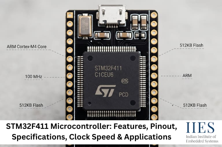
What is STM32F411?
STM32F411 Architecture
The STM32F411 is built around the ARM Cortex-M4 processor and integrates memory, communication peripherals, timers, interrupt handling, and analog modules on a single chip.
Major Architecture Components
- ARM Cortex-M4 CPU
- Nested Vector Interrupt Controller (NVIC)
- Floating Point Unit (FPU)
- Flash Memory
- SRAM
- DMA Controller
- GPIO Ports
- Timers
- ADC
- USART/UART
- SPI
- I2C
- USB OTG FS
- Clock Control Unit (RCC)
- Watchdog Timers
- Power Management Unit
Core Architecture Overview
Component | Purpose |
Cortex-M4 Core | Executes program instructions |
Flash Memory | Stores firmware |
SRAM | Stores variables and runtime data |
NVIC | Handles interrupts efficiently |
DMA | Transfers data without CPU involvement |
GPIO | Interfaces with external hardware |
Timers | Generates delays, PWM, and captures events |
ADC | Converts analog signals to digital values |
RCC | Configures and manages system clocks |
USB OTG FS | Enables USB device or host communication |

STM32F411 Working Principle
The STM32F411 executes firmware stored in Flash memory while using SRAM for temporary data storage. It interacts with external devices through GPIO pins and communication peripherals, processes input data, performs calculations, and controls output devices in real time.
Basic Working Flow
- Power is applied to the microcontroller.
- The reset circuitry initializes the device.
- The system clock is configured.
- Firmware execution starts from Flash memory.
- GPIOs and peripherals are initialized.
- Sensors and external devices exchange data.
- The CPU processes incoming information.
- Output peripherals respond based on program logic.
- Interrupts handle time-critical events.
- The application continues running until power is removed or the device is reset.
Example: Temperature Monitoring System
- ADC reads a temperature sensor.
- CPU converts the ADC value into temperature.
- LCD displays the reading.
- Fan turns ON when the temperature exceeds a predefined limit.
- UART sends temperature data to a PC for monitoring.
STM32F411 Features
The STM32F411 features make it suitable for a wide range of embedded applications, from educational projects to industrial products.
Feature | Description |
Core | ARM Cortex-M4 |
CPU Frequency | Up to 100 MHz |
Architecture | 32-bit |
Floating Point Unit | Yes |
DSP Instructions | Yes |
Flash Memory | Up to 512 KB |
SRAM | Up to 128 KB |
DMA | Multiple channels |
GPIO Pins | Up to 81 (package dependent) |
ADC | 12-bit |
Timers | Advanced, General-purpose, Basic |
USB | USB OTG Full Speed |
SPI | Multiple interfaces |
I2C | Multiple interfaces |
USART/UART | Multiple interfaces |
RTC | Yes |
Watchdog Timers | Independent & Window Watchdog |
Low Power Modes | Supported |
Additional Capabilities
- Fast interrupt response
- Multiple PWM channels
- External interrupt support
- Internal oscillators
- Flexible clock tree
- Bootloader support
- CMSIS compatibility
- HAL and Low-Layer (LL) libraries
- FreeRTOS compatibility
STM32F411 Specifications
Below are the commonly referenced STM32F411 specifications. Exact values may vary depending on the package and specific device variant.
Specification | Value |
CPU | ARM Cortex-M4 |
Maximum Clock Speed | 100 MHz |
Architecture | 32-bit |
Flash Memory | Up to 512 KB |
SRAM | Up to 128 KB |
Operating Voltage | 1.7 V–3.6 V |
ADC Resolution | 12-bit |
DMA | Available |
USB | USB OTG FS |
Timers | Multiple 16-bit & 32-bit |
SPI | Up to 5 |
I2C | Up to 3 |
USART/UART | Up to 6 |
CAN | Not available on most STM32F411 variants |
Package Options | LQFP, UFBGA, WLCSP (variant dependent) |
Operating Temperature | Industrial-grade variants available |
Popular STM32F411 Variants
- STM32F411CEU6
- STM32F411CCU6
- STM32F411RET6
- STM32F411RCT6
- STM32F411VE
Each variant differs in memory size, package type, and available GPIO pins.
STM32F411 Pinout
The STM32F411 pinout varies depending on the package selected, but the functional pin categories remain similar.
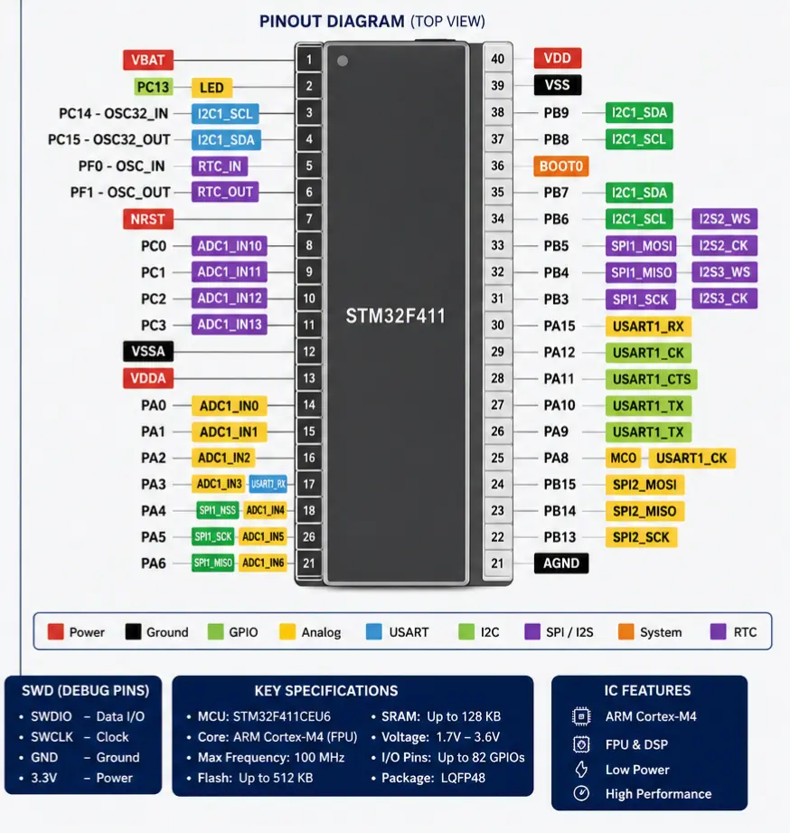
Main Pin Groups
- GPIO Pins
- Power Pins
- Ground Pins
- Reset Pin
- Boot Configuration Pins
- Oscillator Pins
- ADC Input Pins
- PWM Output Pins
- UART Pins
- SPI Pins
- I2C Pins
- SWD Debug Pins
- USB Pins
Important Pins
Pin Group | Function |
VDD | Power supply |
VSS | Ground |
NRST | Hardware reset |
BOOT0 | Boot mode selection |
PA13 | SWDIO |
PA14 | SWCLK |
PA9 / PA10 | USART1 TX/RX |
PA5 | SPI Clock |
PA6 | SPI MISO |
PA7 | SPI MOSI |
PB6 / PB7 | I2C Communication |
PA0–PA7 | GPIO / ADC / Alternate Functions |
Practical Tip
When designing a PCB, reserve the SWDIO, SWCLK, NRST, VDD, and GND pins in the programming header. This simplifies firmware updates, debugging, and production testing without removing the microcontroller from the board.
STM32F411 Clock Speed
One of the most searched specifications is the STM32F411 clock speed. The STM32F411 can operate at a maximum CPU frequency of 100 MHz, enabling it to execute complex embedded applications with low latency and efficient real-time performance.
Clock Sources
- High-Speed Internal Oscillator (HSI)
- High-Speed External Oscillator (HSE)
- Low-Speed Internal Oscillator (LSI)
- Low-Speed External Oscillator (LSE)
- Phase-Locked Loop (PLL)
Why PLL Is Important
The PLL multiplies the input clock frequency to achieve higher system clock speeds while maintaining stable operation. This allows developers to optimize CPU performance without requiring a high-frequency external crystal.
Benefits of a 100 MHz Clock
- Faster instruction execution
- Better real-time response
- Improved communication throughput
- Efficient DSP operations
- Smooth RTOS task scheduling
- Higher PWM resolution
- Better sensor data processing
- Reduced latency in interrupt handling
Practical Design Considerations
- Configure Flash wait states correctly when operating at higher clock frequencies.
- Verify peripheral clock limits before increasing the system clock.
- Use the RCC configuration tools in STM32CubeMX to generate a valid clock tree.
- Higher clock speeds increase power consumption, so select the clock frequency based on application requirements rather than always using the maximum value.
STM32F411 Memory Organization
Understanding the memory organization of the STM32F411 microcontroller helps developers write efficient firmware, optimize RAM usage, and troubleshoot memory-related issues.
Memory Types
Memory | Purpose | Volatile |
Flash Memory | Stores application firmware | No |
SRAM | Stores variables, stack, and heap | Yes |
System Memory | Contains the built-in bootloader | No |
Option Bytes | Stores device configuration settings | No |
Flash Memory
- Stores the compiled program (.hex or .bin file)
- Retains data even after power is removed
- Supports in-application programming (IAP)
- Capacity depends on the STM32F411 variant (up to 512 KB)
SRAM
Used during program execution. Stores:
- Global variables
- Local variables
- Function stack
- Heap memory
- Buffers
SRAM is faster than Flash memory but is cleared after power loss.
System Memory
- Contains the factory-programmed bootloader
- Supports firmware updates through supported interfaces
- Eliminates the need for an external programmer in some applications
Option Bytes
Used to configure:
- Read-out protection
- Brown-out reset level
- Boot configuration
- Write protection
Memory Map (Simplified)
Memory Region | Address |
Flash | 0x08000000 |
SRAM | 0x20000000 |
System Memory | 0x1FFFxxxx (device dependent) |
Peripheral Registers | 0x40000000 |
Practical Tips for Memory Management
- Use const variables to keep fixed data in Flash instead of SRAM.
- Avoid allocating large arrays inside functions, as they consume stack memory.
- Keep interrupt service routines (ISRs) short to prevent excessive stack usage.
- Monitor SRAM usage regularly in STM32CubeIDE during development.
- Use DMA for large data transfers to reduce CPU and memory overhead.
STM32F411 Peripherals
The STM32F411 microcontroller integrates a wide range of peripherals, allowing a single MCU to interface with sensors, displays, motors, communication modules, and storage devices.
Communication Peripherals
Peripheral | Typical Applications |
USART/UART | PC communication, GPS, GSM, Bluetooth |
SPI | Displays, Flash memory, Sensors |
I2C | EEPROM, RTC, Environmental Sensors |
USB OTG FS | USB Device and Host applications |
Analog Peripherals
- 12-bit ADC
- Multiple analog input channels
- Internal temperature sensor
- Internal voltage reference
Common Uses: temperature monitoring, battery voltage measurement, light intensity sensing, potentiometer reading.
Timers
The STM32F411 provides several timer types for timing and control tasks.
Applications: PWM generation, motor speed control, servo control, frequency measurement, event counting, input capture, output compare.
DMA Controller
DMA (Direct Memory Access) transfers data between peripherals and memory without constant CPU intervention.
Benefits:
- Lower CPU utilization
- Faster data transfer
- Improved real-time performance
- Better multitasking with RTOS
Common Applications: UART data reception, SPI communication, ADC continuous conversion, audio streaming.
GPIO
General Purpose Input/Output pins can be configured as:
- Digital Input
- Digital Output
- Alternate Function
- Analog Mode
- External Interrupt
Typical uses include: LEDs, push buttons, relays, sensors, LCD modules, motor drivers.

Is the STM32F411 Microcontroller Good for Beginners?
Yes. The STM32F411 is a good choice for beginners who want to learn modern ARM-based embedded systems after understanding basic C programming and microcontroller concepts.
Why Beginners Choose STM32F411
- Easy-to-use STM32CubeIDE
- Strong community support
- Extensive documentation
- Large number of tutorials
- Affordable development boards
- Professional debugging tools
- Widely used in industry
What You Should Learn First
- C Programming
- Functions
- Pointers
- Structures
- Bitwise Operators
- Digital Electronics
- Basic Microcontroller Concepts
Learning these topics first makes STM32 development much easier.
Common Beginner Challenges
Challenge | Solution |
Clock configuration | Use STM32CubeMX to generate settings |
GPIO configuration | Start with LED blinking examples |
Debugging | Learn ST-LINK debugging tools |
Peripheral setup | Configure peripherals using HAL libraries first |
Datasheet navigation | Focus on the pinout and reference manual sections |
How Do You Program the STM32F411 Microcontroller?
Programming the STM32F411 involves writing firmware, compiling it into machine code, and flashing it onto the microcontroller using a compatible programmer or debugger.
Step 1: Install STM32CubeIDE
STM32CubeIDE combines a code editor, compiler, debugger, and CubeMX configuration tool.
Step 2: Create a New Project
- Open STM32CubeIDE.
- Create a new STM32 project.
- Select the correct STM32F411 device or development board.
- Generate the project.
Step 3: Configure the MCU
Typical configurations include:
- System Clock
- GPIO
- UART
- SPI
- I2C
- ADC
- Timers
Most settings can be configured graphically using CubeMX.
Step 4: Write Embedded C Code
Add your application logic inside the generated project. Example tasks: blink an LED, read a sensor, send UART data, generate PWM, receive SPI data.
Step 5: Build the Project
Compile the code to generate ELF, HEX, and BIN files. Resolve any compilation errors before flashing.
Step 6: Flash the Firmware
- Connect an ST-LINK debugger.
- Build the project.
- Flash the firmware.
- Verify successful programming.
- Reset the board if required.
Step 7: Debug the Program
Use breakpoints to inspect variables, step through code, view registers, monitor memory, and analyze peripheral states. Debugging early helps identify issues before they become difficult to trace.
Which Programming Language Is Used for STM32F411?
The primary programming language for the STM32F411 microcontroller is Embedded C.
Common Languages
Language | Usage |
Embedded C | Most widely used |
C++ | Object-oriented embedded applications |
Assembly | Startup code and performance-critical routines |
Python | Host-side scripting and testing (not executed on the MCU) |
Why Embedded C Is Preferred
- Efficient execution
- Direct hardware access
- Low memory usage
- Industry standard
- Supported by all major embedded toolchains
Common Software Libraries
- CMSIS
- STM32 HAL
- STM32 LL
- FreeRTOS
- USB Middleware
- FATFS
These libraries reduce development time while maintaining flexibility.
HAL vs LL vs Register-Level Programming
Choosing the right programming approach depends on the application’s performance, code size, and development timeline.
Feature | HAL | LL | Register-Level |
Ease of Use | Excellent | Good | Moderate to Difficult |
Performance | Good | Better | Best |
Code Size | Larger | Smaller | Smallest |
Learning Curve | Easy | Moderate | Steep |
Development Speed | Fast | Moderate | Slow |
Hardware Control | Moderate | High | Complete |
HAL
Best for: beginners, rapid prototyping, educational projects, most commercial applications.
LL (Low-Layer)
Best for: faster execution, reduced code size, better peripheral control.
Register-Level Programming
Best for: performance-critical applications, bootloaders, custom drivers, advanced embedded developers.
Practical Recommendation
Start with HAL to understand peripheral configuration and application flow. Move to LL when optimizing performance or reducing code size. Use register-level programming only when you need precise hardware control or maximum efficiency, as it requires a deeper understanding of the STM32 reference manual and peripheral registers.
STM32F411 vs STM32F401: Which Is Better?
Both the STM32F411 and STM32F401 belong to the STM32F4 series and are based on the ARM Cortex-M4 core. They share many features, but the STM32F411 offers higher performance, additional peripherals, and greater flexibility for demanding embedded applications.
STM32F411 vs STM32F401 Comparison
Feature | STM32F411 | STM32F401 |
ARM Core | Cortex-M4 | Cortex-M4 |
Maximum Clock Speed | 100 MHz | 84 MHz |
Floating Point Unit (FPU) | Yes | Yes |
DSP Instructions | Yes | Yes |
Flash Memory | Up to 512 KB | Up to 512 KB |
SRAM | Up to 128 KB | Up to 96 KB |
USB OTG FS | Yes | Yes |
ADC | 12-bit | 12-bit |
SPI Interfaces | Up to 5 | Up to 3 |
I2C Interfaces | Up to 3 | Up to 3 |
USART/UART | Up to 6 | Up to 6 |
DMA | Yes | Yes |
Typical Applications | Robotics, IoT, Industrial Control | General Embedded Applications |
Which Is Better?
For most new embedded projects, the STM32F411 microcontroller is the better choice because it offers higher clock speed, more RAM, better peripheral support, greater scalability, and improved performance for future application expansion.
Advantages of STM32F411
The STM32F411 is widely adopted because it combines high performance with low power consumption and a rich set of integrated peripherals.
Main Advantages
- 32-bit ARM Cortex-M4 architecture
- Up to 100 MHz CPU frequency
- Hardware Floating Point Unit (FPU)
- DSP instruction support
- Up to 512 KB Flash memory
- Up to 128 KB SRAM
- Low power consumption
- Multiple communication interfaces
- Flexible clock configuration
- Rich timer resources
- USB OTG Full-Speed support
- Excellent development ecosystem
- CMSIS compatibility
- FreeRTOS support
- Strong community support
- Affordable development boards
Development Advantages
- Easy project generation using STM32CubeMX
- Official STM32CubeIDE support
- Large collection of software examples
- Reliable debugging using ST-LINK
- Well-maintained HAL and LL libraries
Limitations of STM32F411
Although the STM32F411 is a capable microcontroller, it may not be suitable for every embedded application.
Key Limitations
- Maximum CPU frequency is limited to 100 MHz
- No integrated Ethernet controller
- Most variants do not include a CAN controller
- Limited SRAM compared to higher-end STM32 devices
- No dual-core processing
- Unsuitable for Linux-based applications
- Limited graphics capability without external hardware
Applications of the STM32F411 Microcontroller
The STM32F411 microcontroller is widely used in embedded systems due to its high performance, low power consumption, and versatile peripheral support.
- Industrial Automation: PLCs, machine control, process monitoring, and sensor networks.
- Robotics: Robotic arms, mobile robots, motor control, and autonomous systems.
- Internet of Things (IoT): Smart home devices, environmental monitoring, smart agriculture, and energy management using modules like ESP32, LoRa, GSM, and Bluetooth.
- Medical Electronics: Patient monitoring, portable diagnostic devices, and medical sensors.
- Consumer Electronics: Smart appliances, audio systems, gaming accessories, and home security products.
- Automotive Electronics: Dashboard systems, data loggers, lighting controllers, and battery monitoring.
- Educational Projects: LED blinking, LCD interfacing, weather stations, smart parking systems, and data acquisition projects.
This wide range of applications makes the STM32F411 microcontroller a popular choice for learning, prototyping, and commercial embedded product development.

Conclusion
The STM32F411 microcontroller is an excellent choice for students, hobbyists, and professional developers seeking a high-performance ARM Cortex-M4 platform. With a 100 MHz CPU, hardware Floating Point Unit (FPU), rich peripheral set, and strong software ecosystem, it supports applications ranging from simple LED control to industrial automation and robotics.
For beginners, the STM32F411 offers an accessible learning path through affordable development boards and official tools like STM32CubeIDE. For experienced developers, its performance, flexible peripherals, and compatibility with CMSIS, HAL, LL libraries, and FreeRTOS make it suitable for building reliable embedded products.
If you want to build a career in embedded systems, mastering the STM32F411 microcontroller is a valuable step toward understanding modern ARM-based firmware development. At Join us Indian Institute of Embedded System, practical training with STM32-based projects can help bridge the gap between theoretical concepts and real-world embedded application development.