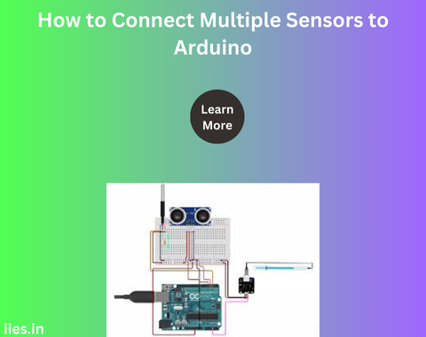
Digital Sensors
Digital sensors provide data in binary form, typically as either a HIGH (1) or LOW (0) signal. Examples include:
- DHT11/DHT22: Humidity and temperature sensors.
- PIR Sensor: Motion detector.
- HC-SR04: Ultrasonic distance sensor.
Analog Sensors
Analog sensors provide data as a range of values, usually between 0 and 1023 for Arduino’s 10-bit ADC (Analog-to-Digital Converter). Examples include:
- Potentiometers: Variable resistors.
- LDR (Light Dependent Resistor): Light sensor.
- LM35: Analog temperature sensor.
Required Components
To connect multiple sensors to an Arduino, you will need:
- Arduino board (e.g., Uno, Mega, Nano)
- Breadboard for prototyping
- Jumper wires for connections
- Sensors (both digital and analog)
- Resistors, if required for specific sensors
- External power supply if additional power is necessary
Steps to Connect Multiple Sensors
1. Plan Your Connections
Carefully plan your wiring before connecting sensors. Identify which pins on the Arduino will be used for each sensor. Digital sensors connect to digital I/O pins, while analog sensors connect to analog input pins.
2. Connect Digital Sensors
When connecting digital sensors:
- Power Supply: Connect the sensor’s VCC pin to the Arduino’s 5V or 3.3V power pin, depending on the sensor’s operating voltage.
- Ground: Connect the sensor’s GND pin to the Arduino’s GND.
- Data Pin: Connect the sensor’s data pin to a designated digital I/O pin on the Arduino.
3. Connect Analog Sensors
When connecting analog sensors:
- Power Supply: Connect the sensor’s VCC pin to the Arduino’s 5V or 3.3V power pin.
- Ground: Connect the sensor’s GND pin to the Arduino’s GND.
- Output Pin: Connect the sensor’s output pin to one of the Arduino’s analog input pins (A0, A1, etc.).
4. Power Management
Ensure that the Arduino can supply enough current to all connected sensors. If using multiple sensors or sensors with high current draw, consider using an external power supply to prevent overloading the Arduino’s power capabilities.
5. Handle Multiple Sensors in Code
While coding, read the values from each sensor within the Arduino’s loop function. Ensure to initialize each sensor properly and handle their readings accordingly. You can print the data to the serial monitor or store it for further processing.
6. Troubleshooting Common Issues
- Incorrect Readings: Verify wiring and sensor specifications. Ensure proper connections and correct pin assignments.
- Power Issues: If sensors are not receiving enough power, use an external power source. Check if the sensors’ current requirements exceed the Arduino’s supply capabilities.
- Library Conflicts: Ensure that you are using compatible libraries for your sensors and that they are correctly installed.

