PCB Design for Modern Electronics – Best Concepts and Powerful Innovations

PCB design tools and best practices

A PCB Design is a fundamental process in electronics that transforms circuit concepts into physical boards. It ensures that electronic devices, from smartphones to spacecraft, function reliably and efficiently. A well-structured PCB design improves performance, reduces errors, and supports manufacturability, making it a vital skill in modern electronics engineering.

A PCB design refers to the step-by-step process of creating schematics, placing components, routing signals, and preparing files for manufacturing. This process is essential for achieving signal integrity, stable power delivery, effective thermal management, and compliance with industry standards in professional electronics applications.

What Is PCB Design in Electronics?

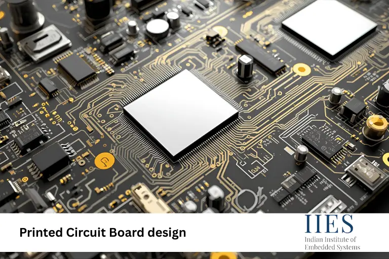
A Printed Circuit Board (PCB) is a flat board that connects and supports electronic components using conductive tracks. PCB design is the process of creating the schematic, layout, and manufacturing files that bring an electronic circuit to life.

Key aspects include:

  • Schematic capture of the circuit
  • PCB layout of components and routing
  • Design verification for signal and power integrity
  • Manufacturing preparation (Gerber, drill, and pick-and-place files)

Without efficient PCB design, modern devices like IoT boards, medical electronics, and aerospace systems would not be possible.

Start Your training Journey Today

PCB Design Process – A Quick Overview

Stage Description Tools Used
Schematic Design Circuit creation, component selection, and ERC Altium, KiCad, Eagle
Board Layout Component placement, routing, layer stack-up ECAD software
Design Verification Signal, power, thermal, EMI/EMC analysis Simulation tools
Manufacturing Prep Gerber/drill files, assembly docs Fabrication software

How Schematic Design Works in PCB Layout

The schematic design is the starting point. Engineers capture the circuit diagram using ECAD software like Altium Designer or KiCad. Components are carefully selected, libraries are managed, and electrical rule checks (ERC) ensure correctness before moving to the layout phase.

Example – Schematic to Board Layout

Imagine designing a microcontroller-based sensor board:

  • In the schematic, you connect the MCU, sensors, and power circuits.
  • In the PCB layout, you place the MCU at the center, route high-speed lines with controlled impedance, and design power planes for stability.
  • Before manufacturing, you run Design Rule Checks (DRC) and generate Gerber files for production.

This flow ensures a smooth and reliable transition from idea to hardware.

Signal Integrity in PCB Design

Signal integrity is crucial in high-speed PCB layout. Poor design can lead to noise, crosstalk, and system failures.

Important techniques:

  • Impedance control with microstrip/stripline traces
  • Crosstalk mitigation by spacing critical signals
  • Length matching in differential pairs (USB, DDR, PCIe)
  • Via optimization to minimize reflection

Power Delivery in PCB Manufacturing

Stable power delivery is essential for reliability. PCB designers use:

  • Dedicated power planes for low impedance
  • Correct decoupling capacitor placement
  • Voltage drop analysis for long traces
  • PDN (Power Distribution Network) optimization for high-speed systems

Thermal Management in PCB Layout

Excessive heat can damage electronics. PCB thermal design includes:

  • Using the proper copper weight for the current flow
  • Thermal vias for heat dissipation
  • Heat sink integration for hot components
  • Via stitching to spread heat evenly.

Explore Courses - Learn More

Modern PCB Technologies (HDI, Flexible, Rigid-Flex)

Modern devices demand advanced PCB technologies:

High-Density Interconnect (HDI) PCB

  • Laser-drilled microvias
  • Sequential lamination
  • Support for fine-pitch BGAs

Flexible & Rigid-Flex PCB

  • Used in aerospace, medical, and wearables
  • Bend radius calculations prevent cracking.
  • Stiffener integration for mechanical stability

High-Speed PCB Design

  • Low-Dk, low-loss substrates
  • Signal conditioning techniques
  • Back drilling to eliminate via stubs

RF/Microwave PCB Design

  • Transmission line optimization
  • Integrated antennas
  • Shielding techniques for EMI reduction

PCB Design Tools and ECAD Software

Designers rely on specialized tools for accuracy:

  • ECAD Software: Altium, Cadence Allegro, KiCad
  • Simulation Tools: Signal integrity, thermal, vibration modeling
  • Version Control: Git for hardware design collaboration

Industry Challenges in PCB Manufacturing

  1. Miniaturization – Smaller packages like 01005 require precise routing
  2. High-Speed Complexity – DDR5, PCIe Gen6 need strict design rules
  3. Supply Chain Issues – Component shortages and obsolescence
  4. Environmental Compliance – Meeting RoHS/REACH and sustainable standards

Future Trends – AI-Assisted and 3D Printed Electronics

The future of PCB design is exciting:

  • Embedded components inside PCB layers
  • Advanced materials with low-loss, stretchable substrates
  • AI-assisted PCB design for automated routing and error prediction
  • 3D printed electronics using conductive ink and additive manufacturing

Summary – PCB Design in Modern Electronics

Factor Importance in PCB Design Example Application
Signal Integrity Clean, reliable signals High-speed DDR memory
Power Delivery Stable voltage levels CPU/GPU boards
Thermal Management Prevent overheating Automotive ECUs
Modern Technologies Compact and flexible designs IoT & wearables

Common Mistakes to Avoid

  • Ignoring signal integrity rules → causes crosstalk.
  • Incorrect decoupling capacitor placement → unstable power
  • Poor thermal design → overheating and failure
  • Not following DFM/DFA rules → manufacturing issues.


Talk to Academic Advisor

Conclusion

Modern printed circuit board design is no longer just about connections; it’s about creating smarter, smaller, and more efficient systems. Engineers who master signal integrity, power distribution, and PCB thermal management will be well-prepared for the next generation of electronics design challenges.

Frequently Asked Questions

PCB design is the process of creating a schematic, layout, and manufacturing files to turn circuits into physical boards.

Signal integrity, power delivery, thermal management, and manufacturing constraints.

 Altium Designer, Cadence Allegro, KiCad, and simulation tools.

 HDI (High-Density Interconnect) uses microvias and fine-pitch routing for compact boards.

It’s fine for small programs, but not recommended in large projects or header files due to conflict risks.

AI-assisted PCB design, embedded components, and 3D printed electronics.