What Is Serial Communication in 8051 Microcontroller?
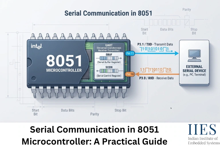
Serial communication in 8051 microcontroller is the process of sending and receiving data one bit at a time over a single line in each direction, using the chip’s on-chip UART. Instead of moving eight bits at once across eight separate lines the way parallel communication does, the 8051 shifts each bit out sequentially on TXD and reads incoming bits sequentially on RXD.
The 8051’s serial port is full-duplex, it can transmit and receive at the same time, because the transmit and receive circuits use two physically separate internal registers, even though both are accessed through the same address. That shared address belongs to SBUF.
Two Port 3 pins carry the signal:
- TXD (P3.1) – transmits outgoing serial data
- RXD (P3.0) – receives incoming serial data
Everything else, mode selection, baud rate, status flags, is handled through two SFRs (Special Function Registers): SBUF and SCON.

How Does Serial Communication Work in 8051?
At the hardware level, the 8051 actually has two separate 8-bit registers, one for transmit, one for receive, that both sit at the same address, 99H. When your code writes to SBUF, the value goes into the transmit register and the UART starts shifting it out. When your code reads from SBUF, it reads from the receive register instead, not the byte you just wrote. That dual-register trick is what makes full-duplex operation possible without one operation clobbering the other.
The SBUF Register
SBUF behaves simply:
- Writing to SBUF starts transmission of that byte.
- Reading from SBUF retrieves the last byte received.
The SCON Register
SCON (Serial Control register, address 98H) is bit-addressable and controls how the serial port behaves:
Bit | Name | Function |
7 | SM0 | Serial mode select bit 0 |
6 | SM1 | Serial mode select bit 1 |
5 | SM2 | Multiprocessor communication enable |
4 | REN | Receive enable, must be 1 to receive data |
3 | TB8 | 9th data bit to transmit (Modes 2 and 3) |
2 | RB8 | 9th data bit received (Modes 2 and 3) |
1 | TI | Transmit interrupt flag |
0 | RI | Receive interrupt flag |
SM0 and SM1 together select which of the four serial modes is active. REN has to be set to 1, or the receiver simply won’t accept incoming data, a detail beginners forget constantly, then spend an hour wondering why RI never gets set.
TI and RI deserve their own callout, because they cause more first-time bugs than anything else in this peripheral:
- TI is set by hardware automatically the moment the last bit of a byte finishes transmitting. Your code checks it (usually by polling) and then has to clear it manually, hardware never clears it for you.
- RI is set by hardware once a complete byte has landed in SBUF. Same rule: your code must clear it before the next byte arrives, or you risk missing data or hanging in a wait loop.
Forgetting to clear TI or RI is probably the single most common mistake in beginner 8051 serial code.
Serial Port Modes in 8051 (Mode 0 to Mode 3)
The 8051 supports four serial modes, selected using the SM0 and SM1 bits in SCON:
Mode | SM0 | SM1 | Type | Baud Rate | Frame |
0 | 0 | 0 | Shift register | Fixed – Fosc/12 | 8 data bits, no start/stop |
1 | 0 | 1 | 8-bit UART | Variable – via Timer 1 | 1 start + 8 data + 1 stop |
2 | 1 | 0 | 9-bit UART | Fixed – Fosc/64 or Fosc/32 | 1 start + 9 data + 1 stop |
3 | 1 | 1 | 9-bit UART | Variable – via Timer 1 | 1 start + 9 data + 1 stop |
Mode 0 isn’t really meant for talking to another UART device – it’s a synchronous shift-register mode, typically paired with an external shift register (like a 74HC164) to add cheap extra output pins. TXD outputs the clock; RXD carries the data.
Mode 1 is what most people actually mean when they say “8051 serial communication.” It’s asynchronous, uses the familiar 10-bit frame (start bit, 8 data bits, stop bit), and its baud rate is generated by Timer 1, which is why you’ll almost always see Timer 1 configured right next to the serial port.
Mode 2 adds a 9th data bit, useful for parity or as an address/data flag in multiprocessor setups, but its baud rate is fixed relative to the oscillator rather than timer-adjustable.
Mode 3 combines the two, 9-bit frames with a Timer-1-driven variable baud rate. It’s the mode to reach for when you need multiprocessor-style addressing and control over speed.
How to Calculate Baud Rate in 8051 Serial Communication
For Modes 1 and 3, the 8051 doesn’t generate the baud rate on its own – it borrows Timer 1, running in Mode 2 (8-bit auto-reload), as a baud rate generator. Every time Timer 1 overflows, it automatically reloads from TH1, and that overflow rate sets your baud rate.
The relationship is:
Baud Rate = (2^SMOD / 32) × Oscillator Frequency / (12 × (256 − TH1))
SMOD is bit 7 of the PCON register; setting it to 1 doubles the baud rate.
Rearranged to solve for TH1 (with SMOD = 0):
TH1 = 256 − [Oscillator Frequency / (384 × Desired Baud Rate)]
Worked Example: 9600 Baud at 11.0592 MHz
This exact combination shows up in almost every 8051 serial communication example you’ll find, and there’s a real reason for it, 11.0592 MHz divides cleanly into the standard baud rates.
TH1 = 256 − (11,059,200 / (384 × 9600))
TH1 = 256 − 3
TH1 = 253 = 0xFD
Load TH1 with 0xFD and you get exactly 9600 baud, with zero error.
Compare that to a 12 MHz crystal, common on plenty of development boards: it doesn’t divide evenly into standard baud rates, so you end up with a small percentage of baud rate error. At lower speeds (2400, 4800 baud) that error is usually small enough that communication still works. Push toward 19200 baud or higher, and the error can grow enough to cause framing errors, which is exactly why 11.0592 MHz became the unofficial standard crystal for 8051 serial projects.

How to Program Serial Communication in 8051 (Step-by-Step)
Here’s the general sequence for setting up and using the serial port, whether you’re sending sensor data, debug messages, or AT commands to a GSM module:
- Set Timer 1 to Mode 2 (8-bit auto-reload) using the TMOD register.
- Load TH1 with the reload value for your target baud rate.
- Configure SCON to select the serial mode and enable reception.
- Start Timer 1 by setting TR1.
- Transmit by writing to SBUF, then wait for TI and clear it.
- Receive by waiting for RI, reading SBUF, then clearing RI.
Here’s what that looks like in Keil C51:
c
#include

void serial_init(void) {

    TMOD = 0x20;   // Timer 1, Mode 2 (8-bit auto-reload)

    TH1  = 0xFD;   // 9600 baud @ 11.0592 MHz

    SCON = 0x50;   // Serial Mode 1, 8-bit UART, REN enabled

    TR1  = 1;      // Start Timer 1

}

void serial_tx(unsigned char byte) {

    SBUF = byte;

    while (TI == 0);   // wait for transmission to finish

    TI = 0;             // clear manually -- hardware won't do it

}

unsigned char serial_rx(void) {

    while (RI == 0);   // wait for a byte to arrive

    RI = 0;

    return SBUF;

}

void serial_tx_string(char *str) {

    while (*str) {

        serial_tx(*str++);

    }

}

void main(void) {

    serial_init();

    serial_tx_string("8051 serial port ready\r\n");

    while (1) {

        unsigned char received = serial_rx();

        serial_tx(received);   // simple echo

    }

}

If you're working in assembly instead, the same logic looks like this:

asm

; Initialize: Mode 1, 9600 baud @ 11.0592 MHz

MOV TMOD, #20H

MOV TH1, #0FDH

MOV SCON, #50H

SETB TR1

; Transmit byte in A

MOV SBUF, A

WAIT_TX: JNB TI, WAIT_TX

CLR TI

; Receive byte into A

WAIT_RX: JNB RI, WAIT_RX

CLR RI

MOV A, SBUF
Both versions do the same thing: configure the timer, set the mode, then poll TI/RI around every send and receive.
Interfacing 8051 Serial Communication with a PC
One detail that catches a lot of beginners off guard: the 8051’s TXD/RXD pins run at TTL logic levels (0V and 5V), while classic RS-232 ports, the DB9 connector on older PCs — use inverted signaling across a range of roughly ±12V. Wire them together directly and communication won’t work reliably; in the worst case, you risk damaging the microcontroller pin.
That’s what a level-shifter IC like the MAX232 is for. It sits between the 8051’s TXD/RXD pins and the RS-232 connector, converting voltage levels in both directions.
If you’re using a modern USB-to-serial adapter instead, FTDI FT232, CP2102, CH340, the kind built into most Arduino boards and cheap USB-serial dongles, you can usually skip the MAX232 entirely. Those adapters work at TTL levels on the microcontroller side and only convert to USB, not true RS-232.
This is exactly how most student and hobbyist 8051 projects log sensor data or debug output to a PC: initialize the serial port as shown above, then send text with serial_tx_string() the same way you’d reach for printf during debugging, and read it in a terminal like PuTTY, Tera Term, or the Arduino Serial Monitor.
Limitations and Practical Considerations
Serial communication in 8051 microcontroller is simple and dependable for what it’s built to do, but it’s worth knowing where it falls short:
- Speed ceiling. UART on the 8051 tops out well below what SPI or I2C can manage at short range, fine for sensor logging or GSM/GPS modules, less ideal for high-throughput data transfer.
- No built-in error correction. Beyond the stop bit acting as a basic framing check, there’s no checksum or CRC, you add that at the application level if you need it.
- Crystal choice matters. As shown above, an 11.0592 MHz crystal gives exact standard baud rates; other crystal values introduce error that worsens at higher baud rates.
- Manual flag management. TI and RI must be cleared in software every single time, miss it once and the next byte either won’t send or won’t register as received.
- Voltage level mismatch. Direct connection to genuine RS-232 hardware needs a level shifter; skipping it is a common way to damage a board.

Conclusion
Serial communication in the 8051 microcontroller comes down to two registers doing most of the work: SBUF moving the actual data, and SCON deciding how that data moves, which mode, whether reception is even enabled, and when a transfer is complete. Once you understand that Timer 1 is what’s really setting your baud rate in Modes 1 and 3, values like TH1 = 0xFD stop looking like a magic number copied from a forum post and start making sense as a calculation you can redo for any crystal or baud rate you need.
If you’re setting this up for the first time, logging sensor data to a PC, talking to a GSM module, or linking two 8051 boards, start with Mode 1 at 9600 baud on an 11.0592 MHz crystal. It’s the most forgiving combination to debug, and the same register logic carries over directly once you move to Modes 2 or 3.