What is Pulse Width Modulation?
Pulse Width Modulation, commonly referred to as PWM, is an electronic technique used to regulate power supplied to electrical devices. It works by rapidly turning a signal ON and OFF at a fixed frequency while varying the duration of the ON time.
The amount of power transferred depends on the pulse width or duty cycle of the signal. A wider pulse delivers more average power, while a narrower pulse delivers less power.
PWM signals are generally square waves that switch between HIGH and LOW states. Because switching occurs at high speed, the output appears smooth and continuous to most electronic systems.
PWM is widely used because it provides:
- High efficiency
- Precise output control
- Reduced heat dissipation
- Better performance in power electronics
- Improved energy management
PWM technology is now a core element in embedded systems, motor control circuits, communication systems, and digital electronics.

PWM Working Principle
Understanding the PWM working principle is essential for learning how modern electronic systems control power efficiently.
In Pulse Width Modulation, the frequency of the signal generally remains constant, but the width of each pulse changes according to the required output power. This variation in pulse width directly changes the average voltage delivered to the load.
For example:
- A 25% duty cycle delivers low average power
- A 50% duty cycle delivers medium power
- A 75% duty cycle delivers high power
The switching process happens so quickly that devices such as motors and LEDs respond smoothly without noticeable interruptions.
A PWM signal is commonly generated using:
The comparator compares the modulating signal with a reference waveform, usually a sawtooth wave. Based on this comparison, the output waveform changes its pulse width.
When the sawtooth signal exceeds the modulating signal, the comparator output changes state, producing the PWM waveform.
What is PWM Duty Cycle?
The PWM duty cycle refers to the percentage of time a signal remains in the ON state during one complete cycle.
It represents the ratio between ON time and total cycle time.
Duty Cycle=ON TimeTotal Time×100Duty\ Cycle = \frac{ON\ Time}{Total\ Time} \times 100Duty Cycle=Total TimeON Time×100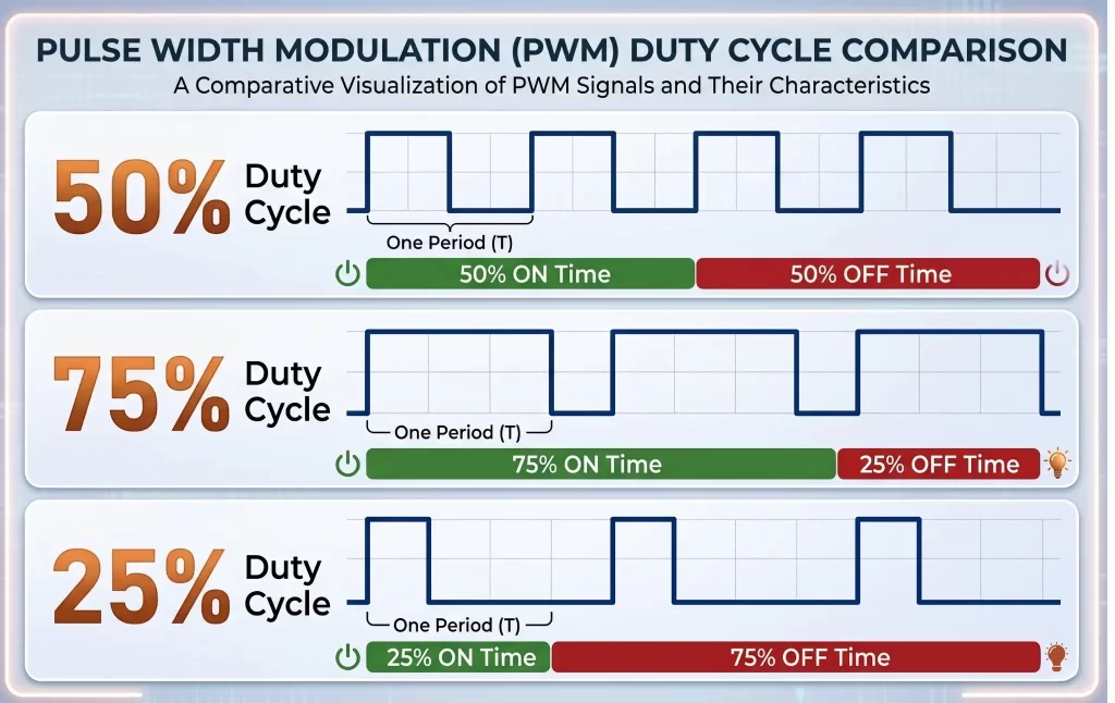
For example:
Duty Cycle | Output Power Level |
10% | Very Low |
50% | Medium |
90% | High |
If a PWM signal has a 50% duty cycle, the signal remains ON for half of the cycle duration and OFF for the remaining half.
The duty cycle is extremely important because it directly determines:
- Motor speed
- LED brightness
- Audio output level
- Power regulation
- Battery charging efficiency
PWM duty cycle control is one of the most effective methods for efficient power management in electronic systems.
Procedure for Producing Pulse Width Modulation
The generation of PWM signals is commonly achieved using a comparator circuit.
The comparator receives two input signals:
- Modulating signal
- Sawtooth reference waveform
The sawtooth waveform acts as the timing reference, while the modulating signal carries the required control information.
When the sawtooth waveform becomes greater than the modulating signal, the comparator output changes state. This process continuously generates pulses with varying widths.
Each cycle produces a pulse whose width corresponds to the modulating signal level. The sequence of varying pulses forms the PWM output waveform.
This technique is widely used in:
- Embedded systems
- Power electronics
- Motor drivers
- Switching regulators
- Communication systems
Types of PWM
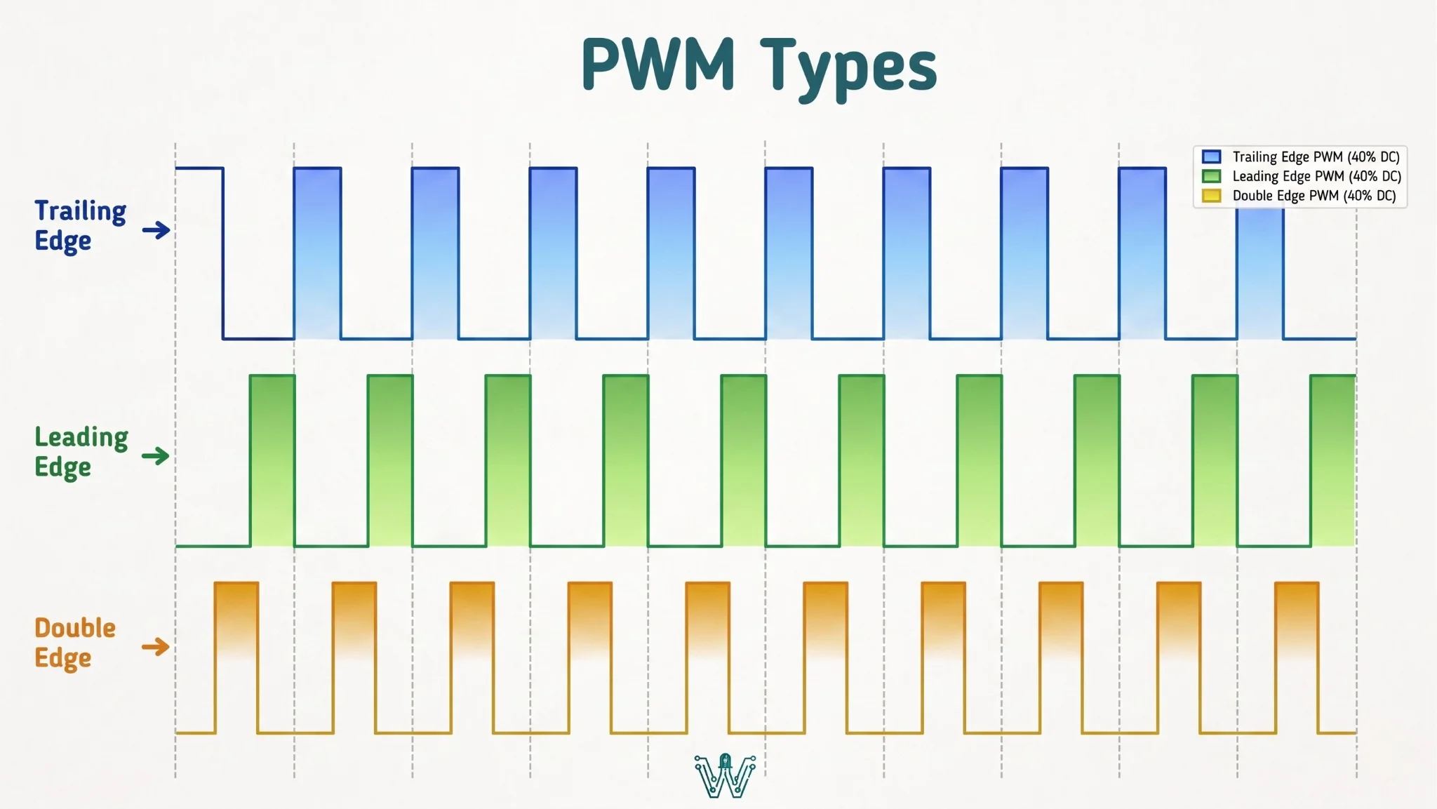
There are several PWM modulation techniques used depending on application requirements.
Trail Edge Modulation
In Trail Edge Modulation, the rising edge remains fixed while the falling edge changes according to modulation requirements.
This technique maintains a constant frequency while varying the duty cycle.
Applications include:
- LED brightness control
- Power regulation
- Lighting systems
- Industrial dimmers
Because the frequency remains stable, it helps reduce flickering in LED lighting applications.
Lead Edge Modulation
Lead Edge Modulation changes the leading edge of the waveform while keeping the trailing edge fixed.
This method controls the average power delivered to the load by modifying the pulse start timing.
Lead edge PWM is widely used in:
- LED drivers
- Motor control systems
- DC power supplies
- Battery-powered electronics
Pulse Centre Two Edge Modulation
Pulse Centre Two Edge Modulation, also known as Dual Edge Modulation, changes both leading and trailing edges of the pulse.
This technique provides better waveform symmetry and improved harmonic performance.
Applications include:
- Motor drives
- Voltage inverters
- Industrial automation
- Advanced power electronics
Among the different types of pulse width modulation techniques, this approach is highly effective in reducing switching noise.
What Are the Applications of PWM?
Pulse width modulation applications are present in both consumer electronics and industrial systems. PWM enables precise control, energy efficiency, and reliable operation across multiple industries.
PWM in Motor Speed Control
One of the most common PWM applications is motor speed control.
Instead of changing voltage continuously, PWM rapidly switches the motor supply ON and OFF. The average power determines the motor speed.
How Does PWM Control Motor Speed?
A higher duty cycle increases motor speed because the motor receives more average power. A lower duty cycle reduces speed.
PWM motor control is widely used in:
- Electric scooters
- Robotics
- CNC machines
- Electric vehicles
- Cooling fans
- Industrial automation systems
For example, in electric scooters, twisting the throttle changes the PWM duty cycle generated by the controller. This directly controls wheel speed efficiently while reducing overheating and mechanical wear.
PWM in LED Brightness Control
PWM is extensively used in LED lighting systems.
Instead of reducing voltage directly, LEDs are switched rapidly ON and OFF. Human eyes perceive this as dimming or brightness adjustment.
Advantages include:
- Better energy efficiency
- Reduced power consumption
- Consistent color quality
- Longer LED lifespan
PWM-based LED dimming is widely used in:
- Smart lighting
- Automotive headlights
- Display systems
- Decorative lighting
PWM in Robotics
Robotics applications use PWM for controlling:
- Servo motor direction
- DC motor speed
- Robotic arm movement
- Sensor systems
Servo motors rely heavily on PWM signals for precise angular positioning. This makes PWM essential in automation and robotics engineering.
PWM in Solar Energy Systems
PWM technology is used in solar charge controllers to regulate battery charging from solar panels.
The controller adjusts charging current efficiently, protecting batteries from:
- Overcharging
- Excessive heating
- Power fluctuations
PWM solar charge controllers are widely used in residential and industrial renewable energy systems.
PWM in Audio Systems
Class D audio amplifiers use PWM techniques to generate high-efficiency audio output signals.
Compared to traditional amplifiers, PWM amplifiers:
- Generate less heat
- Consume less power
- Deliver better efficiency
This technology is commonly used in:
- Bluetooth speakers
- Home theater systems
- Car audio systems
PWM in Telecommunication Systems
PWM is also used in telecommunications for encoding digital information onto analog carrier signals.
Applications include:
- Remote controls
- Signal transmission
- Wireless communication
- Audio transmission systems
PWM in Arduino and Embedded Systems
Pulse Width Modulation is widely used in Arduino and embedded systems to control motors, LEDs, sensors, and servo motors efficiently. By adjusting the PWM duty cycle through built-in microcontroller PWM pins, developers can achieve precise control of speed, brightness, and output power without using complex analog circuits.
Popular microcontrollers that support PWM functionality include:
PWM is widely used in beginner and advanced embedded projects such as:
- LED brightness control systems
- Smart fan speed controllers
- Servo motor positioning systems
- Line-following robots
- Automated irrigation systems
- Home automation devices
- IoT-based monitoring systems
In Arduino LED dimming projects, PWM controls LED brightness efficiently by adjusting the duty cycle. In robotics, PWM enables smooth DC motor speed control for precise movement, making it an essential technique in embedded systems and microcontroller programming.

Industries That Use PWM Technology
Pulse Width Modulation is widely used across multiple industries because of its efficiency, precision, and reliable power control capabilities. PWM technology plays a major role in:
- Automotive systems
- Industrial automation
- Consumer electronics
- Robotics
- Renewable energy systems
- Aerospace applications
- Medical equipment
- Telecommunications
From electric vehicles and smart appliances to industrial motor drives and solar power systems, PWM has become an essential technology in modern electronics and embedded systems.
Advantages of PWM
PWM provides several important advantages in modern electronics.
High Efficiency
Since switching devices operate mainly in fully ON or OFF states, power loss is minimized.
Reduced Heat Generation
PWM reduces unnecessary power dissipation, helping prevent overheating in electronic circuits.
Precise Control
PWM allows highly accurate control over:
- Speed
- Brightness
- Voltage
- Torque
- Power delivery
Cost-Effective Design
PWM systems eliminate the need for complex analog control circuits.
Better Battery Performance
PWM improves energy management, especially in battery-operated devices and electric vehicles.
Comparison of PWM Applications
Application | Purpose of PWM | Benefits |
Motor Control | Speed regulation | Efficient operation |
LED Lighting | Brightness adjustment | Energy saving |
Robotics | Servo positioning | Precision control |
Solar Systems | Battery charging | Improved battery life |
Audio Amplifiers | Signal amplification | Reduced heat |
Telecommunications | Signal encoding | Reliable transmission |
Future Trends of PWM in 2026 and Beyond
PWM technology continues evolving with modern electronics and smart systems.
Emerging trends include:
Electric Vehicles
Advanced PWM controllers are improving motor efficiency and battery optimization in EVs.
Smart Home Automation
PWM is increasingly used in smart lighting, intelligent fans, and IoT-enabled appliances.
AI-Based Motor Control
Industrial systems are integrating AI algorithms with PWM controllers for adaptive power management.
Renewable Energy Integration
PWM plays a major role in smart solar inverters and sustainable energy systems.
Advanced Robotics
Future robotics systems will use high-frequency PWM for smoother motion and precise automation.
As industries move toward energy-efficient systems, PWM applications will continue expanding rapidly.
Common Mistakes to Avoid in PWM Design
Engineers and beginners often encounter challenges while implementing PWM systems.
Common mistakes include:
- Using incorrect PWM frequency
- Choosing poor duty cycle ranges
- Ignoring heat management
- Improper filtering
- Electromagnetic interference issues
- Incorrect motor driver selection
Proper circuit design and frequency optimization are essential for achieving stable PWM performance.
Best Practices for PWM Implementation
To improve PWM system efficiency:
- Select suitable switching frequencies
- Use proper heat sinks
- Optimize duty cycle ranges
- Apply filtering techniques
- Choose efficient MOSFET drivers
- Reduce switching noise through PCB optimization
These practices improve system reliability and operational efficiency.
Challenges and Limitations of PWM
Although PWM provides high efficiency and precise control, it also has some limitations. High-frequency switching can generate electromagnetic interference (EMI) and electrical noise. Incorrect PWM frequency may cause LED flickering, audible motor noise, overheating, or reduced efficiency. Poor filtering can also introduce ripple and instability in sensitive electronic systems.
Some additional limitations of PWM include:
- Increased circuit complexity in advanced systems
- Heat generation in switching components at very high frequencies
- Harmonic distortion in power electronics
- Requirement for proper shielding and PCB design
To overcome these issues, engineers commonly use:
- Noise filters
- Heat sinks
- Optimized PWM frequencies
- Shielded circuit layouts
- Efficient MOSFET drivers
- Proper grounding techniques
Despite these limitations, PWM remains one of the most efficient and widely used power control techniques in modern electronics and embedded systems.

Conclusion
Pulse Width Modulation has become a foundational technology in modern electronics, enabling efficient and precise power control across countless applications. From robotics and electric vehicles to LED lighting and renewable energy systems, pulse width modulation applications continue transforming how electronic devices operate.
Understanding what is PWM, PWM working principle, PWM duty cycle, and different PWM techniques is essential for engineers, students, and electronics enthusiasts working with embedded systems and power electronics.
As technology advances toward automation, energy efficiency, and intelligent control systems, PWM will remain a key technique driving innovation across industries.
Businesses and engineers adopting advanced PWM controllers and optimized PWM techniques can achieve better performance, lower energy consumption, and longer system lifespan in future electronic designs.