It is likely that you have encountered a “Hello World!” program as a code example during your study of a programming language. Gaining an understanding of the basic principles of that language is not only helpful but also offers you a competitive edge in that setting. If you are interested in learning a new programming language, it may be beneficial to search for a “Hello World!” program code online to begin your journey. The program explained here serves a comparable purpose for the 8051 microcontroller This is the most straightforward task to undertake.
LED Control / Activation
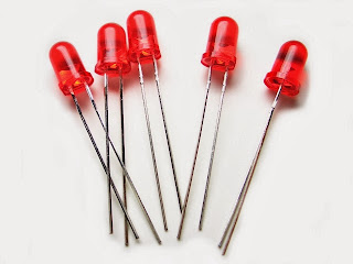
Light Emitting Diodes, commonly known as LEDs, are straightforward lighting solutions that allow for easy ON/OFF operation. They seem to have a certain familiarity with the illustration provided beneath.

The extended leg corresponds to the POSITIVE terminal, while the shorter leg clearly denotes the NEGATIVE terminal. When using your legs, ensuring their care is crucial. The symbol used to represent an LED in diagrams is as shown, so ensure you do not get confused. The left side of the terminal is marked as POSITIVE, in contrast to the right side, which is marked as NEGATIVE.

Establishing a connection between an LED and the 8051 Microcontroller
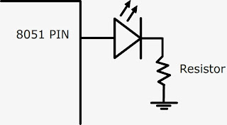
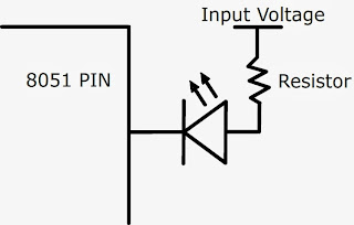
There are two authentic approaches to connect an LED to your 8051 microcontroller. Both options will function effectively, yet they employ contrasting programming methodologies.

LED INTERFACE CIRCUIT_1

LED INTERFACE CIRCUIT_2
The resistor plays a crucial role in interface 2 by regulating the current flow, thereby protecting both the LED and the MCU from potential damage. However, the resistor in interface 1 is not a significant concern since the 8051 MCU is incapable of damaging the LED. That said, we should avoid discussing safety issues.
I will thoroughly elucidate the details of the program code Allow me to provide you with a conceptual insight regarding the distinction between these two interfaces.
- The LED associated with Interface 1 will light up exclusively if the PIN value is HIGH, demonstrating that current is flowing down to ground.
- The LED The LED at circuit_2 will activate if and only if the the PIN value is zero/low.
Source Code
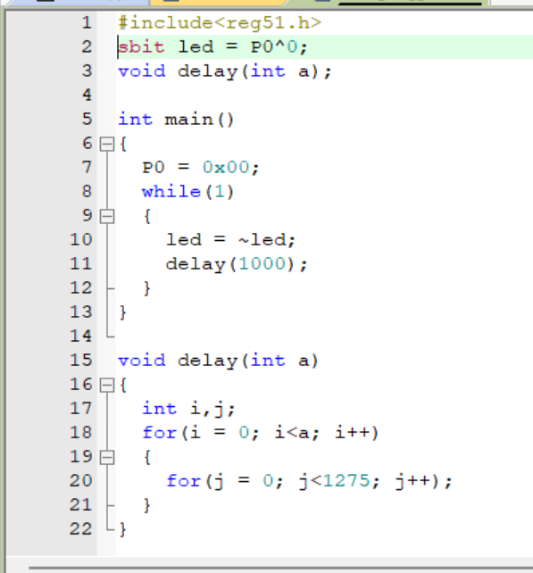
Let’s dive right into the code at this point. I will outline the details of C Language code, so let’s get underway. I believe you are well-acquainted with creating a HEX file through KEIL and simulating the code using PROTEUS. Once you have finished verifying your code, you can continue with the subsequent tasks Programming the 8051 MCU is a straightforward process.
For hands-on evaluation, implementing a test circuit for the 8051 MCU is a fundamental requirement of the project, and it is necessary to ensure successful outcomes. Once you become accustomed to it, the process is quite straightforward.

It is apparent that the task of writing in C language becomes increasingly straightforward. Employ conventional C operators for the manipulation of data and values. It is essential in this code to provide the MCU with a perpetual task, as this is considered best practice. (Utilizing a while loop that runs indefinitely) This will ensure that it remains trapped in the loop, ceasing all movement and simply gazing at you. It must perpetually engage in a designated task.
This code utilizes a general delay function that effectively delivers the desired delay in milliseconds, as determined by the input parameter. When we refer to delay (1000), we are indicating a pause of one second. While you may use this function for the moment, it is advisable to avoid it in scenarios where timing is essential and accuracy is paramount, for the accurate delay we need to go for the peripheral called Timers/Counters. By proper configurations of timers the delay and generation of wave forms can be done very easily.
The value of PIN0.0 continuously alternates between ON and OFF after a certain delay. The implementation of the delay is achieved through the use of nested loops. For the time being, it is adequate to mention that the delay lasts long enough for the human eye to detect the blinking of the LED.


