1. Overview of STM32 Timers
Timers are peripheral devices that make it possible to generate PWM signals, measure time precisely, and carry out recurring tasks. A variety of timer types, each with unique capabilities appropriate for various applications, are available on STM32 microcontrollers.
Types of STM32 Timers
Simple timers (TIM6, TIM7, etc.): Basic features like counting and time delays are available with these timers. They lack sophisticated functions like PWM generation, output comparison, and input capture.
TIM2, TIM3, and TIM4 are examples of general-purpose timers: These are multipurpose timers that accommodate numerous functions, such as:
PWM output
Capturing input (quantifying pulse width or signal frequency)
Comparing output (producing time-triggered events)
Timers with advanced control (TIM1, TIM8, etc.): These timers are made for more complicated uses, like motor control, where it’s necessary to have multiple PWM channels with synchronized outputs.
Watchdog Timers: In the event of a software malfunction or hang, these timers are used to reset the microcontroller. Both window watchdog timers (WWDG) and independent watchdog timers (IWDG) are available on the STM32.
Key Features of the Timer
Prescaler: Allows for longer time periods by lowering the timer’s clock frequency.
Counter: A register (which, depending on the timer, may be 16-bit or 32-bit) that counts clock pulses.
Period: The number at which the timer will stop counting and reset.
PWM Generation: To control devices like motors or LEDs, timing devices can produce Pulse Width Modulation (PWM) signals. Measure the timing properties of an external signal, such as its frequency or pulse width, using input capture. Output Compare: When a predetermined count value is reached, initiate an event (such as an interrupt).
2. Making Use of STM32 Timer
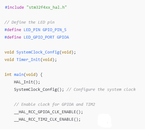
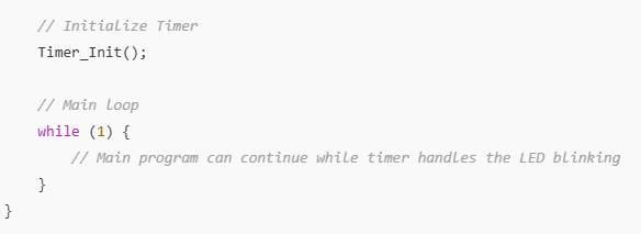
Let’s look at a simple example of using a timer to control a basic LED and create a time delay. The ability of the timer to manage time-based events without utilizing a blocking delay function will be illustrated in this example.
An example of a timer is an LED that blinks.
In this example, an STM32 timer will be set up to produce an interrupt once every second, which will then be used to toggle an LED.
Turn on Timer Clock: To begin, turn on the desired timer’s clock (such as TIM2).
Set up the timer: To get a 1-second time period, set the timer’s prescaler and period.
Turn on Interrupts: Turn on the timer’s interrupt, which will start when the timer goes over.
Routine for Interrupt Service (ISR): Indicate which interrupt handler toggles


TIM2 is set up in this example to overflow and cause an interrupt once every second. The LED on GPIO pin PA5 is toggled by the interrupt service routine.
3. Overview of STM32 Interrupts
The microcontroller can react to events asynchronously thanks to interrupts, which eliminate the need for a continuous loop of peripheral or sensor status checks. The processor switches to an interrupt service routine (ISR) to handle the event when an interrupt is triggered, pausing the ongoing execution.
Types of STM32 Interrupts
External Interruptions: produced by external pins, such as GPIO pins that are set up as inputs.
Timer interruptions: When timers reach their predetermined duration or experience other circumstances (such as overflow), they generate timer interrupts. ADC, UART, SPI, and other peripherals can cause peripheral interrupts.
System Interrupts: These comprise fault interrupts (e.g., HardFault) and system tick timers (SysTick).
Interrupt Handling in STM32:
- Interrupts need to be enabled in the NVIC (Nested Vector Interrupt Controller) as well as the peripheral (such as a timer).
- At the point when a interruptions happens, a capability known as the Interfere with Administration Routine (ISR) is run. Since interruptions are typically time-sensitive, it needs to be quick and effective.
- Clearing Interrupt Flags: The interrupt will continue to trigger if the interrupt flag is not cleared after the ISR has completed.
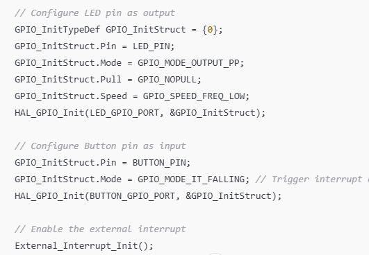
Example: Pressing a Button Causes an External Interrupt This illustration shows how to set up an external interrupt to occur in response to the pressing of a button attached to PA0.
Turn on GPIOA Clock: Turn on the GPIOA clock so it can reach PA0.
Set up PA0 as an interrupt-equipped input: Enable the interrupt for this pin and set PA0 as an input.
Interrupt Service Routine: When the button is pressed, the LED in the ISR is toggled.
Here’s how to put this into practice:


In this model, the ISR flips the Drove on PA5 after a button on PA0 causes an interfere.
4. Essential Ideas for Timers and Interrupts Timer:
Prescaler: To slow down the counting process, the prescaler divides the timer’s input clock. The period specifies how many timer counts must pass before the timer overflows and causes an interruption.
Interrupt Enable: If you want the timer to cause an interrupt when it overflows, you must enable the timer interrupt.
Disruptions: The Nested Vectored Interrupt Controller, or NVIC, manages interrupt execution and priorities.
Interrupt Flags: In order to recognize an interrupt, a flag associated with each interrupt source must be cleared.
Priority: There are various levels at which interruptions can be ranked. Lower-priority interruptions are superseded by higher-priority ones.
Conclusion
Timers and interrupts are essential features of STM32 microcontrollers for handling time-based events and asynchronous input/output. Timers offer precise control over time and can generate periodic events like PWM signals, while interrupts allow the system to respond immediately to events, minimizing the need for constant polling.
By combining these two features, STM32 developers can create efficient, responsive systems that handle a wide range of real-time tasks in embedded applications. Understanding how to configure and use timers and interrupts is fundamental for developing time-critical applications with STM32 microcontrollers.


