1.What is PWM (Pulse Width Modulation)?
PWM is a technique that uses a digital signal to simulate an analog signal by varying the amount of time the signal is on (high) versus the amount of time it is off (low) in each cycle.
The duty cycle is the ratio of on-time to off-time.
High signal (ON): The time the signal is “on” or at its maximum value;
Low signal (OFF): The time the signal is “off” or at its minimum value;
Duty cycle: The percentage of time the signal is “on” in a single full cycle.
An example of a PWM signal is 50% duty cycle: The signal is on for half the time and off for the other half; 25% duty cycle: The signal is on for 25% of the time and off for 75%.
PWM is used in many applications, including controlling the brightness of LEDs, motor speed, and even audio generation.
2. How PWM Operates?
PWM generates a square wave, and the duty cycle and wave frequencyor how many times the wave repeats per second control the signal’s behavior. The partnership is:
The frequency,expressed in Hz,is the number of cycles per second.Smoother output is the effect of higher frequency. Duty cycle: The proportion of a cycle that the signal is active.This regulates the typical amount of power applied to a load.
3. Arduino PWM
Digital pins on Arduino boards are capable of producing PWM signals. PWM signals can be found on pins 3, 5, 6, 9, 10, and 11 of the majority of Arduino boards. A PWM signal is produced on a specified pin using the function analog Write(pin, value). Pin: The pin number, which needs to be able to handle Value: PWM, with 255 representing full on (100% duty cycle) and 0 representing full off (0% duty cycle).
4. Useful PWM Examples in Arduino Projects
4.1 Managing the Brightness of LEDs
- Managing an LED’s brightness is one of the most popular applications for
- The duty cycle can be changed to alter the LED’s apparent brightness
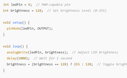
Example of Code:

By varying the duty cycle from 50% (128) to 100% (255), this code regulates the LED brightness.
4.2 Managing the Speed of the Motor PWM is also used to regulate DC motor speed. The duty cycle can be changed to regulate the motor’s rotational speed.
4.3 Audio Production (Generating Tone) PWM is also useful for producing sound. You can generate different tones by altering the signal’s frequency.
5. PWM Frequency Considerations and Limitations:
Depending on the pin, PWM signals on Arduino normally have a frequency of 490 Hz or 976 Hz. For many purposes, this is typically acceptable, but for more exact control, it would need to be modified.
Heat and Efficiency: Because PWM signals turn on and off rather than continuously supplying full power, it can help save energy and minimize heat when regulating motors or other power-hungry equipment.
6. Complex PWM Methods
Although basic PWM is straightforward, more sophisticated methods exist for modifying PWM signals to produce more intricate behaviors: Adjusting the PWM frequency is possible with certain Arduino libraries, which is useful for applications like motor control where a greater or lower frequency may be required. Multiple Devices: You can use several PWM signals to simultaneously control multiple devices for more complicated projects.
Final thoughts
A strong and effective method for managing analog,like behavior with digital signals is pulse width modulation (PWM).With Arduino, it is simple to implement and can be used to control motors, LEDs, and even create sound.Comprehending PWM isessential for numerous Arduinobased applications and creates numerous opportunities for accurate device control.

