As a key component in electronic circuits, resistors play a crucial role in managing and limiting the flow of electrical current. Recognizing the behavior of resistors in diverse configurations, such as series and parallel, is key to designing circuits that work optimally.
- Resistors in Series
In a series connection, resistors are placed one after another, establishing a single route for the current to pass. A defining characteristic of a series circuit is that the current is consistent across all resistors.
Key Points about Resistors in Series:
- Current: Each resistor experiences the same current flow because there is only one pathway available for the current to traverse.
- Total Resistance: The combined resistance (Rtotal) in a series circuit is determined by summing the resistances of each component. In mathematical terms, this is articulated as:
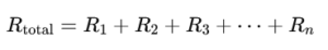
R1, R2, R3, through Rn denote the resistances of each individual resistor.
- Voltage: In accordance with Kirchhoff’s Voltage Law, the cumulative voltage across resistors connected in series is the total of the voltages measured across each resistor.
Example:
Imagine three resistors with values of 2Ω, 3Ω, and 5Ω connected in a series configuration. The cumulative resistance will be:
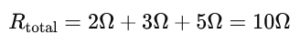
With a total voltage of 10V supplied to the circuit, the voltage across each resistor will change according to its resistance, while the current remains consistent throughout.
- Resistors in Parallel
In a parallel configuration, the resistors are attached across identical two points, which establishes multiple channels for the current to move through. The most notable aspect of a parallel circuit is that every resistor has the same voltage across it.
Key Points about Resistors in Parallel:
- Voltage: Every resistor connected in parallel shares the same voltage across its terminals.
- Current: The source supplies a total current that is shared among the parallel branches, with each resistor handling a fraction of that current.
- Total Resistance: To determine the total resistance in a parallel circuit, the reciprocal formula is utilized.
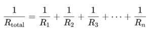
This formula indicates that the total resistance in a parallel circuit will always be less than the resistance of the smallest individual resistor within that circuit.
Example:
Envision three resistors, each with resistances of 2Ω, 3Ω, and 6Ω, linked in parallel. The overall resistance can be calculated using the following method:
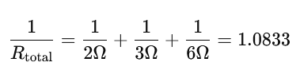
Consequently, the cumulative resistance Rtotal It would be roughly 0.923Ω.
Analyzing Resistors Configured in Series and Parallel
- In Series: The total resistance grows when more resistors are incorporated into the system. The current remains constant across each resistor, while the voltage is distributed among them.
- In Parallel: The overall resistance reduces when more resistors are included in the circuit. Each resistor maintains a constant voltage, yet the total current experiences an increase.
Practical Applications:
- Series Circuits: Employed in situations that require an increase in total resistance, this is particularly relevant in light bulbs, allowing for brightness control based on varying resistance.
- Parallel Circuits: Household electrical systems often feature devices connected in parallel, which ensures that all devices receive the same voltage and that the malfunction of one does not disrupt the operation of the others.
Conclusion
It is vital for those engaged in electronics to comprehend the behavior of resistors when arranged in series and parallel. Series circuits lead to an increase in overall resistance and distribute voltage across the components, while parallel circuits lower the total resistance and maintain a constant voltage. Mastering these concepts enables you to develop circuits that are not only more efficient but also more functional, suitable for a range of applications from simple gadgets to sophisticated systems