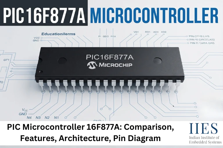
What Is the PIC16F877A Microcontroller?
The PIC16F877A is a general-purpose 8-bit microcontroller designed for embedded control applications. It belongs to the PIC16 family of Microchip microcontrollers and is based on a Harvard architecture with a Reduced Instruction Set Computer (RISC) design.
Unlike a general-purpose processor, the PIC16F877A is built to perform dedicated tasks in electronic systems while consuming low power and requiring minimal external hardware.
Main Characteristics
- 8-bit CPU
- Harvard Architecture
- RISC Instruction Set
- Flash Program Memory
- EEPROM Data Memory
- SRAM
- Multiple Timers
- PWM Module
- 8-channel ADC
- UART Communication
- SPI Interface
- I²C Interface
- Interrupt Support
- Watchdog Timer
PIC16F877A Full Form
The name PIC16F877A contains useful information about the microcontroller family.
Part | Meaning |
PIC | Peripheral Interface Controller |
16 | PIC16 mid-range microcontroller family |
F | Flash program memory |
877 | Device number |
A | Improved revision of the original PIC16F877 |
The “A” version includes improvements over the original PIC16F877, making it the preferred choice for most embedded applications.
PIC16F877A Microcontroller Features
The PIC16F877A integrates several hardware peripherals that reduce the need for external components and simplify embedded system development.
Feature | Specification |
CPU | 8-bit RISC |
Maximum Operating Frequency | 20 MHz |
Instruction Cycle | 200 ns |
Program Memory | 8K × 14-bit Flash |
Data RAM | 368 Bytes |
EEPROM | 256 Bytes |
GPIO Pins | 33 |
ADC | 8-channel, 10-bit |
Timers | Timer0, Timer1, Timer2 |
PWM Modules | 2 CCP Modules |
UART | Yes |
SPI | Yes |
I²C | Yes |
Interrupts | Multiple sources |
Operating Voltage | 2V–5.5V |
Oscillator Support | External Crystal, RC Oscillator |
Package | 40-pin DIP / 44-pin PLCC |
Major Feature Categories
CPU
- 8-bit architecture
- RISC instruction set
- High execution efficiency
- Simple instruction decoding
Memory
- Flash program memory
- SRAM for variables
- EEPROM for permanent storage
Communication
Analog Features
- 10-bit ADC
- Eight analog channels
Control Features
- Timers
- PWM
- Capture
- Compare
- Interrupt Controller
- Watchdog Timer

PIC16F877A Architecture
The architecture of the PIC16F877A is designed to execute instructions efficiently while supporting multiple peripherals for embedded control applications.
Unlike processors that use a single memory space for both instructions and data, the PIC16F877A follows the Harvard Architecture, allowing program memory and data memory to be accessed independently. This improves instruction execution speed compared to traditional Von Neumann architecture.
Main Architectural Components
- CPU
- Program Memory
- Data Memory
- EEPROM
- ALU
- Working Register (W Register)
- Program Counter
- Stack
- Timers
- ADC
- Interrupt Controller
- Oscillator Circuit
- GPIO Ports
- USART
- SPI
- I²C
- CCP Modules
Architectural Highlights
Harvard Architecture
- Separate program and data memory
- Simultaneous instruction fetch and data access
- Faster execution
RISC Design
- Reduced instruction set
- Most instructions execute in one instruction cycle
- Simplifies firmware development
CPU Core Components
The CPU consists of:
- Arithmetic Logic Unit (ALU)
- W Register
- Status Register
- Program Counter
- Stack
- Instruction Decoder
These components work together to fetch, decode, and execute instructions while interacting with memory and peripherals.
PIC16F877A Block Diagram
The PIC16F877A block diagram shows how the CPU, memory, clock, and peripherals are connected inside the microcontroller. Understanding this block diagram helps you visualize how data flows between different hardware modules while the program is running.
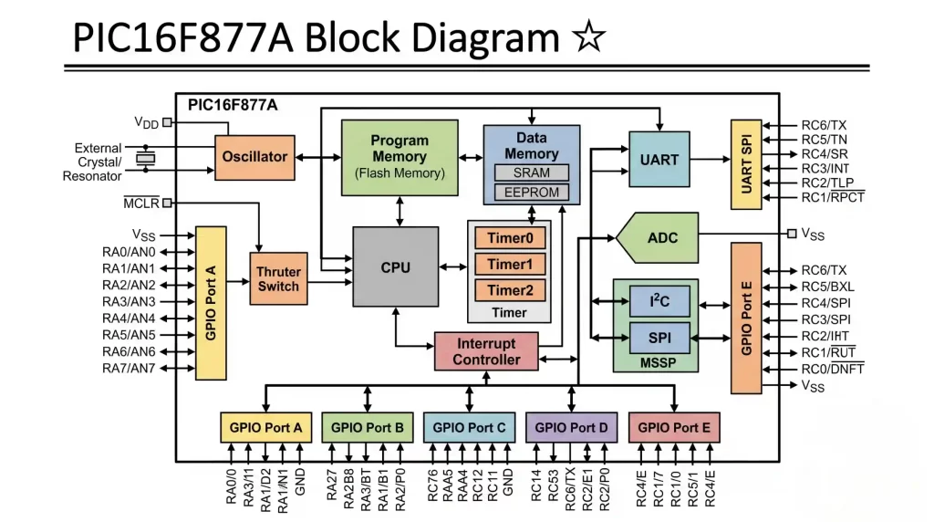
PIC16F877A internal block diagram
Main Blocks of the PIC16F877A
- CPU Core
- Flash Program Memory
- Data RAM
- EEPROM
- Program Counter (PC)
- Stack
- Arithmetic Logic Unit (ALU)
- W (Working) Register
- Oscillator Circuit
- Timer0, Timer1, Timer2
- Interrupt Controller
- ADC Module
- CCP1 and CCP2 Modules
- USART
- SPI/I²C (MSSP)
- GPIO Ports (PORTA–PORTE)
- Watchdog Timer (WDT)
How the Block Diagram Works
- The oscillator generates the clock signal.
- The CPU fetches instructions from Flash memory.
- Instructions are decoded and executed by the ALU.
- Variables are stored in SRAM.
- Permanent user data is stored in EEPROM.
- Peripherals such as ADC, Timers, UART, SPI, and I²C communicate with external devices.
- Interrupts temporarily pause the current program to handle important events.
PIC16F877A Pin Configuration and Description
The PIC16F877A is available in a 40-pin Dual Inline Package (DIP) and a 44-pin PLCC package. It provides 33 programmable GPIO pins, making it suitable for applications that require multiple sensors, displays, communication modules, and actuators.
Pin Categories
- Power Pins
- Oscillator Pins
- Reset Pin
- Digital I/O Ports
- Analog Input Pins
- Communication Pins
- Timer Pins
- PWM Pins
- Programming Pins
Power Pins
Pin | Description |
VDD | Positive supply voltage |
VSS | Ground |
Notes:
- Requires a stable 5V supply for normal operation.
- Place a 0.1 µF decoupling capacitor close to each VDD-VSS pair to reduce electrical noise.
Oscillator Pins
Pin | Description |
OSC1 | Oscillator input |
OSC2 | Oscillator output |
These pins connect to:
- Crystal Oscillator
- Ceramic Resonator
- External Clock
- RC Oscillator
A 20 MHz crystal is commonly used to achieve the maximum operating speed.
Master Clear (Reset)
Pin | Description |
MCLR | External Reset Input |
Functions:
- Resets the microcontroller
- Starts program execution from the reset vector
- Used during programming
A 10 kΩ pull-up resistor is typically connected between MCLR and VDD.
PIC16F877A Pin Diagram and Port Functions
The PIC16F877A has five I/O ports: PORTA, PORTB, PORTC, PORTD, and PORTE. Each port can perform digital I/O operations, while many pins also support alternate peripheral functions.
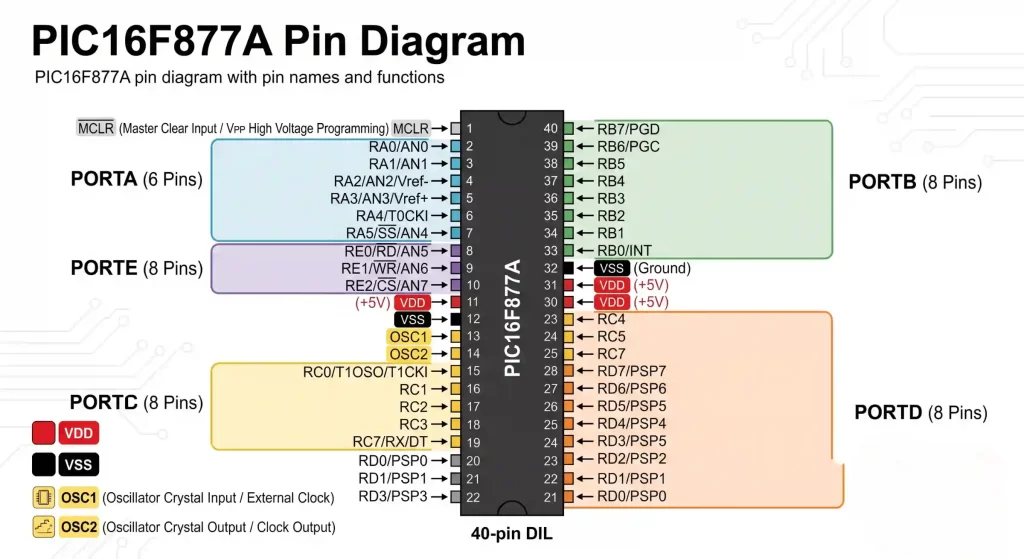
PIC16F877A Pin Diagram
PORTA
Pins | Functions |
RA0–RA5 | GPIO, Analog Inputs, Timer Functions |
Supports:
- ADC Channels
- Timer0 Clock Input
- Comparator Functions (device dependent)
Common uses: temperature sensors, light sensors, voltage measurement.
PORTB
Pins | Functions |
RB0–RB7 | Digital I/O, External Interrupts |
Features:
- External Interrupt (INT)
- Interrupt-on-Change
- Internal Pull-up Resistors
Common uses: push buttons, switches, keypads.
PORTC
Pins | Functions |
RC0–RC7 | Communication & PWM |
Supports:
- UART
- SPI
- I²C
- CCP1
- CCP2
- Timer1 Oscillator
Common uses: Bluetooth modules, GSM modules, sensors, motor drivers.
PORTD
Pins | Functions |
RD0–RD7 | Digital I/O |
Mostly used for LCD interfacing, data buses, and parallel communication.
PORTE
Pins | Functions |
RE0–RE2 | Analog Inputs and Control Signals |
Used for ADC channels and Parallel Slave Port functions.
Memory Organization of the PIC16F877A
The PIC16F877A uses three different memory types, each serving a different purpose, allowing the microcontroller to execute code efficiently while retaining important data even after power is removed.
Memory Type | Purpose |
Flash Memory | Stores program code |
SRAM | Stores temporary variables |
EEPROM | Stores permanent user data |
Flash Program Memory
Features:
- 8K × 14-bit words
- Non-volatile
- Stores firmware
- Can be reprogrammed many times
Used for: embedded C program, boot code, control algorithms.
SRAM
Features:
- 368 Bytes
- Fast read/write
- Volatile memory
Used for: variables, buffers, counters, flags. Contents are lost when power is removed.
EEPROM
Features:
- 256 Bytes
- Non-volatile
- Read/write during program execution
Common uses: user settings, calibration values, passwords, device IDs.
Working Principle of the PIC16F877A
The PIC16F877A continuously executes instructions stored in Flash memory using the Fetch–Decode–Execute cycle.
Step 1 – Fetch
The CPU fetches an instruction from Flash memory using the Program Counter.
Step 2 – Decode
The instruction decoder identifies the required operation.
Step 3 – Execute
The ALU performs arithmetic or logical operations, updates registers, and controls peripherals if required.
This cycle repeats continuously until the microcontroller is reset or powered off.
CPU and Instruction Set
The PIC16F877A is based on an 8-bit RISC architecture.
Key Characteristics
- 35 simple instructions
- Most instructions execute in one instruction cycle
- Separate instruction and data memory
- Efficient instruction pipeline
Benefits
- Faster execution
- Simpler programming
- Reduced code complexity
Timers in the PIC16F877A
Timers are hardware counters used for measuring time, generating delays, counting external events, and producing periodic interrupts.
Timer0
Features: 8-bit timer, internal or external clock, prescaler support.
Applications: delay generation, event counting, LED blinking.
Timer1
Features: 16-bit timer, internal or external clock, high-resolution timing.
Applications: RTC projects, frequency measurement, precise delays.
Timer2
Features: 8-bit timer, prescaler and postscaler, PWM support.
Applications: PWM generation, motor speed control, audio signal generation.
ADC (Analog-to-Digital Converter)
The PIC16F877A includes an 8-channel 10-bit ADC.
Features:
- 10-bit resolution
- Eight analog input channels
- Configurable voltage reference
Common applications: temperature sensing, battery monitoring, light sensors, pressure sensors, potentiometers.
CCP Modules (Capture, Compare, PWM)
The PIC16F877A provides two CCP modules.
Capture Mode
Used to measure pulse width, signal frequency, and time intervals.
Compare Mode
Used for event generation, timer comparison, and output control.
PWM Mode
Generates Pulse Width Modulation signals for DC motor control, servo motor control, LED brightness control, and power converters.
USART (UART Communication)
USART enables serial communication with computers and external devices.
Applications: PC communication, GPS modules, GSM modules, Bluetooth modules, serial debugging.
Supported modes: Asynchronous UART, synchronous communication.
SPI Interface
SPI is a high-speed synchronous communication protocol.
Commonly connected devices: EEPROM, SD cards, LCD displays, DACs, ADCs, sensors.
Advantages: high speed, full-duplex communication, simple implementation.
I²C Interface
The MSSP module also supports the I²C protocol.
Applications: RTC modules, EEPROM, OLED displays, environmental sensors, I/O expanders.
Advantages: two-wire communication, supports multiple slave devices, reduces wiring complexity.
Interrupt System
Interrupts allow the microcontroller to respond immediately to important events without continuously checking peripheral status.
Common Interrupt Sources
- External Interrupt (RB0/INT)
- Timer0 Overflow
- Timer1 Overflow
- Timer2 Overflow
- ADC Completion
- USART Receive
- USART Transmit
- CCP Interrupt
- EEPROM Write Completion
Benefits
- Faster event response
- Better CPU utilization
- Reduced software polling
- Improved real-time performance
Oscillator Modes
The PIC16F877A supports multiple clock configurations.
Oscillator Mode | Typical Use |
LP | Low-power crystal |
XT | Standard crystal oscillator |
HS | High-speed crystal oscillator |
RC | External resistor-capacitor oscillator |
The oscillator selection depends on the application’s speed, power consumption, and accuracy requirements.
PIC Microcontroller Families
Microchip offers several PIC microcontroller families designed for different performance and application requirements.
PIC Family | Description | Common Applications |
PIC10 | Ultra-small, low-pin-count MCUs | Simple control circuits, sensors |
PIC12 | 8-pin microcontrollers | Consumer electronics, IoT nodes |
PIC16 | Mid-range 8-bit microcontrollers | Education, industrial control, automation |
PIC18 | High-performance 8-bit microcontrollers | USB devices, communication systems |
PIC24 | 16-bit microcontrollers | Medical devices, motor control |
dsPIC33 | 16-bit Digital Signal Controllers | Motor drives, power electronics, DSP |
PIC32 | 32-bit microcontrollers | IoT, networking, industrial automation |
How to Choose a PIC Microcontroller
Choose a PIC microcontroller based on your application’s memory requirements, processing performance, communication interfaces, operating voltage, and available peripherals.
- PIC16F877A – Best for learning embedded systems, GPIO, ADC, timers, PWM, UART, SPI, and I²C.
- PIC16F887 – Choose when you need more analog input channels while keeping a similar 8-bit architecture.
- PIC18F4550 – Ideal for USB-based applications and projects requiring more program memory.
- PIC18F46K22 – Suitable for advanced embedded systems with larger Flash memory, RAM, and additional peripherals.
- PIC24 – Recommended for applications requiring higher processing performance and lower power consumption.
- dsPIC33 – Best for digital signal processing, motor control, and power conversion.
- PIC32 – Designed for high-performance applications such as IoT gateways, networking devices, and industrial automation.
Recommendation: If you are learning embedded systems or building your first microcontroller project, the PIC16F877A is one of the best starting points. Once you’re comfortable with its architecture and peripherals, moving to the PIC18, PIC24, dsPIC33, or PIC32 families becomes much easier.

PIC16F877A vs Arduino vs STM32 vs AVR vs ESP32
Feature | PIC16F877A | Arduino Uno (ATmega328P) | STM32F103 | ESP32 |
Architecture | 8-bit PIC | 8-bit AVR | 32-bit ARM Cortex-M3 | Dual-core Xtensa LX6 |
Maximum Clock | 20 MHz | 16 MHz | 72 MHz | Up to 240 MHz |
Flash Memory | 8K Words | 32 KB | 64–128 KB | Up to 16 MB (module dependent) |
RAM | 368 Bytes | 2 KB | 20 KB | 520 KB |
ADC | 8-channel, 10-bit | 6-channel, 10-bit | 12-bit ADC | 12-bit ADC |
PWM | Yes | Yes | Yes | Yes |
UART | Yes | Yes | Multiple | Multiple |
SPI | Yes | Yes | Yes | Yes |
I²C | Yes | Yes | Yes | Yes |
Wi-Fi | No | No | No | Yes |
Bluetooth | No | No | No | Yes |
Best For | Learning embedded fundamentals | Hobby projects | Industrial applications | IoT and wireless systems |
How to Program a PIC Microcontroller with Arduino
An Arduino can be used as an ICSP (In-Circuit Serial Programming) programmer for a PIC16F877A. This is a low-cost option for learning and basic projects, but for regular development, a PICkit programmer is recommended for better compatibility and debugging support.
Requirements
Hardware
- Arduino Uno, Nano, or Mega
- PIC16F877A Microcontroller
- Jumper wires
- Breadboard
- 5V power supply
Software
- Arduino IDE
- MPLAB X IDE
- MPLAB XC8 Compiler
- Arduino-compatible PIC programming software
Arduino to PIC16F877A Connections
Arduino | PIC16F877A | Function |
5V | VDD | Power |
GND | VSS | Ground |
Programming Data* | RB7 (PGD) | Data |
Programming Clock* | RB6 (PGC) | Clock |
Reset Control* | MCLR | Programming Mode |
*The Arduino pins used depend on the programmer firmware or sketch.
Programming Steps
- Write and compile your program in MPLAB X IDE using the XC8 Compiler.
- Generate the HEX file.
- Upload the PIC programmer firmware to the Arduino.
- Connect the Arduino to the PIC16F877A using the ICSP pins.
- Load the HEX file and program the PIC.
- Reset the microcontroller and verify that the application runs correctly.
Advantages
- Low-cost programming solution
- Suitable for learning and educational projects
- No dedicated programmer required
Limitations
- Slower than a PICkit programmer
- Limited device support
- No hardware debugging
Note: Arduino-based programming is suitable for learning, while PICkit 4 or PICkit 5 is the preferred option for reliable programming and debugging of the PIC16F877A.
Common Applications of the PIC Microcontroller 16F877A
The PIC Microcontroller 16F877A is widely used in embedded systems that require reliable control, sensor interfacing, and real-time processing. Despite the availability of modern 32-bit microcontrollers, it remains a popular choice for education, industrial automation, and embedded product prototyping.
- Industrial Automation: Motor control, PLC systems, process monitoring, temperature controllers
- Consumer Electronics: Digital clocks, home appliances, electronic locks, smart lighting
- Robotics: Line follower robots, robotic arms, obstacle avoidance robots
- Automotive Electronics: Dashboard indicators, battery monitoring, lighting and door control
- Medical Devices: Digital thermometers, patient monitoring systems, medical data loggers
- IoT Projects: Interfacing with ESP8266, ESP32, GSM, LoRa, and Zigbee modules for wireless communication
- Educational Projects: Traffic light controllers, water level indicators, RFID attendance systems, smart irrigation, electronic voting machines, and fire alarm systems
Advantages of the PIC16F877A
The PIC16F877A remains a popular learning platform because it combines essential peripherals with a straightforward architecture.
- Simple RISC architecture
- Easy to learn for beginners
- Reliable operation
- Large developer community
- Extensive documentation
- Flash-based reprogrammable memory
- Built-in EEPROM
- Multiple communication interfaces
- Multiple timers
- PWM support
- ADC support
- Low component count
- Wide operating voltage range
- Available in DIP package for breadboard prototyping
- Long-standing support from Microchip
Disadvantages of the PIC16F877A
Despite its strengths, the PIC16F877A has limitations compared to modern microcontrollers.
- 8-bit architecture
- Limited RAM (368 Bytes)
- Limited Flash memory
- Maximum clock frequency of 20 MHz
- No built-in USB
- No built-in CAN controller
- No Ethernet interface
- No Wi-Fi
- No Bluetooth
- Limited processing power for complex applications
- Less suitable for AI, machine learning, and advanced graphics
Applications requiring wireless connectivity or high-performance processing are generally better served by devices such as the ESP32 or STM32 families.
Conclusion
The PIC Microcontroller 16F877A continues to be an excellent platform for learning embedded systems despite the availability of more powerful microcontrollers. Its simple RISC architecture, integrated peripherals, and extensive documentation make it suitable for students, hobbyists, and professionals building embedded applications.
By understanding its architecture, memory organization, communication interfaces, timers, ADC, and GPIO configuration, you develop the core skills required to design reliable embedded systems. These fundamentals also make it easier to transition to advanced microcontroller families as project requirements evolve.