What Is the Structure of a Raspberry Pi?
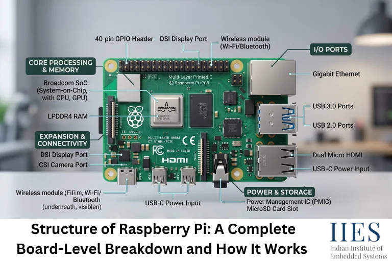
At its core, a Raspberry Pi is a single-board computer (SBC): a complete computer, processor, memory, storage interface, and I/O, built onto one PCB, instead of being spread across a motherboard with separate expansion cards.
The structure breaks down into a few functional layers:
- Processing layer – the SoC, which contains the CPU cores and GPU
- Memory layer – RAM soldered directly onto the board (no DIMM slots)
- I/O layer – GPIO, USB, Ethernet, camera/display, audio, and expansion interfaces
- Power layer – voltage regulation, the power connector, and (on newer boards) a power button and battery-backed real-time clock
- Storage layer – a microSD card slot, plus PCIe-based expansion for NVMe storage on newer models
Every Raspberry Pi model arranges these layers slightly differently, but the underlying logic is the same: keep the CPU/GPU close to memory, and route everything a user touches (GPIO, USB, HDMI) to the edges of the board.

Raspberry Pi Architecture at a Glance
Before looking at individual components, it helps to understand the overall data path.
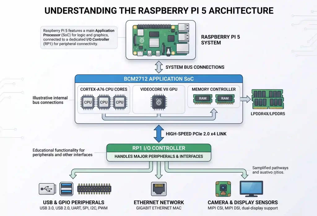
This is a simplified conceptual diagram rather than a complete schematic. The exact signal routing depends on the Raspberry Pi model.
How Does the Raspberry Pi’s Architecture Work?
Understanding the structure is easier once you see how power and data actually move through the board from the moment you apply power.
- Power-on, The board receives 5V through USB-C (or GPIO pins 2/4, if you’re powering it that way). Onboard regulators step this down to the voltages the SoC, RAM, and I/O chip need.
- Boot ROM executes, A small boot ROM inside the SoC runs first. It doesn’t know about an operating system yet; its only job is to find and load firmware from a defined boot source (microSD, NVMe, network, or USB, depending on configuration).
- SoC and GPU initialize, Once firmware loads, the CPU cores and VideoCore GPU come online. On models with RP1, the SoC also brings up the PCIe link to that chip.
- I/O controller enumerates peripherals, The GPIO header, USB ports, Ethernet, and camera/display connectors become active. On the Raspberry Pi 5, this is RP1’s job, not the main SoC’s.
- Operating system boots, Linux (typically Raspberry Pi OS) loads from storage, and kernel drivers bind to each piece of hardware, GPIO chip, USB controller, network interface, and so on.
- User-space access, Once the OS is up, your Python or C code can read GPIO states, talk over I2C/SPI, or push video output, all routed through the same physical structure that came alive during boot.
This flow matters practically: if you’re debugging why a GPIO pin isn’t responding on a Pi 5, for example, you’re not chasing a problem in the main CPU – you’re likely looking at RP1 and its driver, because that’s the chip actually driving the pin.
Key Components on the Raspberry Pi Board
Here’s what you’ll physically find on a modern Raspberry Pi (using the Raspberry Pi 5 as the reference point, since it’s the current flagship model as of 2026), and what each block does.
Processor (SoC)
The Raspberry Pi 5 uses a Broadcom BCM2712 SoC – a 16-nanometer chip built around a quad-core 64-bit Arm Cortex-A76 processor running at 2.4GHz, with 512KB of L2 cache per core and a 2MB shared L3 cache. It’s a direct architectural step up from the BCM2711 used in the Raspberry Pi 4, offering roughly 2–3x the CPU performance.
Graphics Processor (GPU)
Graphics are handled by an 800MHz VideoCore VII GPU, supporting OpenGL ES 3.1 and Vulkan 1.3. It drives dual 4K60 display output and handles camera image processing through a redesigned image signal processor.
Memory (RAM)
RAM sits directly on the board as LPDDR4X-4267 SDRAM, available in multiple capacities (1GB, 2GB, 4GB, 8GB, and 16GB depending on the variant you buy). Because it’s soldered rather than socketed, you choose your RAM size at purchase — there’s no upgrading later.
RP1 I/O Controller
This is the structural change that sets the Raspberry Pi 5 apart from earlier boards. Instead of the main SoC handling every peripheral directly, a second Raspberry-Pi-designed chip called RP1 takes over I/O duties: the 40-pin GPIO header, USB 3.0/2.0 ports, Gigabit Ethernet, and camera/display transceivers. RP1 connects back to the BCM2712 SoC over a PCIe link, which is why I/O throughput improved noticeably over the Pi 4.
A standard 40-pin header, unchanged in physical layout since the Raspberry Pi 2, providing 3.3V-logic general-purpose I/O along with dedicated power and ground pins. On the Pi 5, these pins are controlled by RP1 rather than the SoC directly.
Storage Interfaces
A microSD card slot (supporting high-speed SDR104 mode) serves as the primary boot storage on most builds. A PCIe 2.0 x1 interface is also exposed, letting you attach an NVMe SSD through a separate HAT for faster, more reliable storage.
Power Management
Power comes in over USB-C (5V/5A, with USB Power Delivery support), passing through onboard regulation before reaching the SoC, RAM, and RP1. The Pi 5 also adds a dedicated power button and a battery-backed real-time clock (RTC), so the board can keep accurate time even when powered off, something earlier models didn’t have without an add-on.
Connectivity
Dual-band 802.11ac Wi-Fi, Bluetooth 5.0/BLE, and Gigabit Ethernet (with PoE+ support via a separate HAT) round out the wireless and wired connectivity.
Display and Camera Interfaces
Two 4-lane MIPI transceivers handle camera and display connections, alongside dual micro-HDMI ports for direct monitor output.

Understanding the GPIO Structure on a Raspberry Pi
Because GPIO is where most embedded projects actually connect to the outside world, it deserves its own look.
The 40-pin header uses two numbering schemes that regularly confuse beginners:
- Physical pin numbers (1- 40), the literal position on the connector, counted left to right, top to bottom.
- BCM (Broadcom) GPIO numbers (0 – 27), the logical pin number your code actually references, which doesn’t match the physical position.
A few things worth knowing before you wire anything up:
- GPIO pins operate at 3.3V logic, not 5V. Feeding a 5V signal into an unpowered pin can damage it.
- On the Raspberry Pi 5, GPIO pins are 5V-tolerant only while the board is powered, thanks to RP1 – but this isn’t a substitute for proper level shifting in a production design.
- Pins default to a 50kΩ pull resistance unless configured otherwise in software.
- Many pins double up as alternate functions, I2C, SPI, UART, PWM, selectable through the pin’s alternate-function settings.
If you’re moving from Pi 4 to Pi 5 firmware wise: the physical header hasn’t changed, but the underlying controller has, so drivers, gpiochip numbering, and some UART overlays needed updates to work correctly.
Raspberry Pi Board Structure Across Models
The core building blocks stay consistent, but how much silicon and I/O each model packs in varies a lot. Here’s how the current lineup compares structurally.
Feature | Raspberry Pi 5 | Raspberry Pi 4 | Raspberry Pi Zero 2 W |
SoC | BCM2712 (16nm) | BCM2711 (28nm) | RP3A0 (quad-core A53) |
CPU | Quad-core Cortex-A76 @ 2.4GHz | Quad-core Cortex-A72 @ 1.5–1.8GHz | Quad-core Cortex-A53 @ 1GHz |
I/O handling | Separate RP1 controller over PCIe | Handled directly by SoC | Handled directly by SoC |
RAM | 1–16GB LPDDR4X | 1–8GB LPDDR4 | 512MB LPDDR2 |
Storage expansion | microSD + PCIe (NVMe via HAT) | microSD only | microSD only |
USB | 2x USB 3.0, 2x USB 2.0 | 2x USB 3.0, 2x USB 2.0 | 1x micro-USB (OTG) |
Form factor | Full-size board | Full-size board | Compact/embeddable |
The practical takeaway: if your project needs to squeeze into a tight enclosure or run on minimal power, the Zero 2 W’s simpler, SoC-only structure is the better fit. If you need PCIe-speed storage or heavier compute, the Pi 5’s split SoC/RP1 structure is what gives it the headroom.
Why This Structure Matters for Embedded Projects
Advantages:
- Splitting I/O onto RP1 (Pi 5) frees the main SoC from interrupt-heavy peripheral handling, improving overall responsiveness.
- A consistent 40-pin GPIO layout across generations means HATs and existing wiring largely carry forward.
- Onboard PCIe support opens the door to NVMe storage and other high-speed peripherals without needing a separate computer.
Limitations to plan around:
- Soldered RAM means you must decide on capacity at purchase – there’s no field upgrade.
- The RP1 architectural shift means drivers and firmware written for older Pi models don’t always behave identically on the Pi 5; test before assuming compatibility.
- Running a full Linux OS on this structure means boot times and real-time determinism are nowhere near what a bare-metal microcontroller (like an STM32 or an 8051) offers, the Raspberry Pi’s structure is built for general-purpose computing with I/O access, not hard real-time control.
Practical Applications Where Raspberry Pi’s Structure Is Put to Work
- Edge AI and computer vision – the CPU/GPU combination handles lightweight inference workloads locally, without needing a cloud round-trip.
- IoT gateways – GPIO, I2C, and SPI interfaces let it aggregate data from multiple sensors before forwarding it over Ethernet or Wi-Fi.
- Robotics controllers – GPIO and PWM output drive motor controllers, while the CPU handles higher-level decision logic.
- Industrial HMIs and dashboards – the display output and networking stack support local control panels for machinery.
- Compact servers – Gigabit Ethernet, PCIe-based storage, and enough RAM headroom make it viable for lightweight self-hosted services.

Conclusion
The structure of a Raspberry Pi isn’t arbitrary – every block on the board exists to solve a specific problem: getting power in cleanly, keeping the CPU fed with memory, and exposing enough I/O for real-world projects without turning the board into a rat’s nest of wiring. Once you understand how the SoC, RAM, RP1 (on newer models), and GPIO header relate to each other, reading a pinout diagram or debugging a flaky peripheral stops being guesswork. That structural understanding is also what separates someone who can follow a wiring tutorial from someone who can actually design around the board’s constraints.