Why STM32F411RE for PWM Motor Control?
The STM32F411RE combines performance, flexibility, and powerful peripherals that make it ideal for motor control applications.
Key Features for Motor Control
- ARM Cortex-M4 core running up to 100 MHz
- Advanced TIM peripherals with multiple PWM channels
- High-resolution prescalers and auto-reload registers
- Dead-time insertion and complementary outputs
- DMA support for real-time duty cycle updates
These features allow developers to build precise, low-latency, and reliable motor control systems, which are essential in robotics, automation, EV systems, and industrial electronics.
Understanding these hardware strengths is a critical first step in any STM32F411RE microcontroller tutorial.
Understanding PWM at the Hardware Level
PWM is a digital technique used to generate an analog-like output by varying the duty cycle of a square wave.
Key PWM Parameters
- Frequency – How fast the PWM signal switches
- Duty Cycle – Percentage of ON time in one PWM period
PWM and Motor Speed
- Higher duty cycle → Higher motor speed
- Lower duty cycle → Lower motor speed
In STM32 microcontrollers, PWM is generated using hardware timers, where a counter value is continuously compared with a Capture/Compare Register (CCR).
This hardware-based approach ensures high accuracy and minimal CPU load, making it ideal for real-time motor control.
This principle forms the foundation of DC motor control using STM32F411RE PWM.

Timer Architecture in STM32F411RE
The STM32F411RE includes multiple timer types suitable for PWM generation:
Timer Types
- Advanced-Control Timer: TIM1
- General-Purpose Timers: TIM2–TIM5
For professional motor control training, TIM1 is especially important.
TIM1 Motor Control Features
- Center-aligned PWM
- Dead-time insertion
- Break and fault protection
- Complementary outputs
Timer Registers Overview
- Prescaler (PSC) – Divides the system clock
- Auto-Reload Register (ARR) – Defines PWM period
- Capture/Compare Register (CCR) – Controls duty cycle
This structure enables fine-grained control over PWM frequency and resolution, forming the backbone of professional STM32F411RE PWM configuration.
STM32F411RE Pin Diagram for PWM and Motor Control Applications
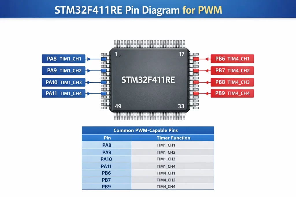
Understanding the STM32F411RE pin diagram is essential before configuring PWM or connecting a motor driver.
The STM32F411RE (LQFP64 package) provides multiple GPIO pins that support alternate functions (AF), including PWM outputs.
Common PWM-Capable Pins
| Pin | Timer Function |
|---|
| PA8 | TIM1_CH1 |
| PA9 | TIM1_CH2 |
| PA10 | TIM1_CH3 |
| PA11 | TIM1_CH4 |
| PB6 | TIM4_CH1 |
| PB7 | TIM4_CH2 |
| PB8 | TIM4_CH3 |
| PB9 | TIM4_CH4 |
These pins must be configured in Alternate Function mode to output PWM signals.
Pin Selection Guidelines
- Prefer advanced timers (TIM1) for motor control
- Verify alternate function mapping from datasheet
- Keep PWM pins close to motor driver inputs
- Always ensure common ground between MCU and driver
Practical DC Motor Control Setup
A typical DC motor using STM32F411RE PWM configuration includes:
- One PWM pin (e.g., PA8 – TIM1_CH1) → Motor driver enable
- Two GPIO pins → Motor direction control (IN1, IN2)
- External motor driver (L298N, L293D, or MOSFET H-bridge)
This approach cleanly separates speed control (PWM) from direction control (GPIO), improving system safety and design clarity.
PWM Signal Design Considerations
1. PWM Frequency
- Typical DC motor range: 1 kHz – 20 kHz
- Higher frequency → Less audible noise
- Higher frequency → Increased switching losses
2. PWM Resolution
- Higher ARR → Finer duty cycle control
- Trade-off between frequency and resolution
3. Motor Driver Interface
- STM32 GPIO pins cannot drive motors directly
- External drivers are mandatory
These constraints are critical in real-world embedded design and STM32F411RE embedded systems training.
STM32 PWM Configuration Flow
- Enable clock for GPIO and timer (RCC)
- Configure GPIO pin in Alternate Function mode
- Set timer prescaler and auto-reload register
- Select PWM Mode 1 or Mode 2
- Enable preload registers
- Start the timer counter
Understanding this low-level flow helps learners master both bare-metal programming and HAL-based development.

Duty Cycle Control and Motor Speed Regulation
Motor speed is controlled by updating the CCR value while keeping the PWM frequency constant.
Example
- CCR = 25% of ARR → Low speed
- CCR = 75% of ARR → High speed
This technique is known as STM32F411RE duty cycle control.
Advanced Techniques
- ADC-based speed control (potentiometer)
- Acceleration and deceleration ramps
- DMA-based duty cycle updates
These methods closely resemble industrial motor control systems.
Direction Control and H-Bridge Integration
PWM controls speed, but direction control requires an H-bridge.
Typical Method
- GPIO 1 → Forward direction
- GPIO 2 → Reverse direction
- PWM → Enable pin
This approach is widely used in robotics, automation, and embedded control systems.
Safety and Protection Mechanisms
Professional motor control designs must handle fault conditions.
STM32F411RE Safety Features
- Break input (BKIN) for emergency shutdown
- External over-current protection
- Dead-time insertion to prevent shoot-through
Teaching these features prepares learners for automotive and industrial-grade embedded applications.
Common Mistakes in PWM Motor Control
- Incorrect alternate function selection
- Inappropriate PWM frequency
- No common ground between MCU and driver
- Attempting to drive motors directly from GPIO pins
Debugging these issues builds strong practical embedded skills.
Learning Outcomes
After completing this tutorial, learners will be able to:
- Understand PWM generation at register level
- Configure STM32 timers for motor control
- Interface motor drivers safely
- Implement speed and direction control
- Apply industrial PWM design principles
These skills are essential for careers in robotics, automation, EV systems, and IoT hardware development.