ESP32 Architecture Overview
The ESP32 is a low-power, high-performance dual-core microcontroller developed by Espressif Systems. It integrates wireless communication, processing units, memory modules, security features, and peripheral interfaces into a single chip.
At a high level, the ESP32 architecture consists of:
- Dual-core Xtensa LX6 processor
- SRAM memory
- ROM memory
- Flash memory interface
- Wi-Fi module
- Bluetooth module
- GPIO pins
- ADC and DAC
- SPI interface
- I2C communication
- UART communication
- PWM generation modules
- Power Management Unit (PMU)
- Security and encryption engine
Each block performs a specific function that contributes to the overall operation of the microcontroller.

ESP32 Functional Block Diagram
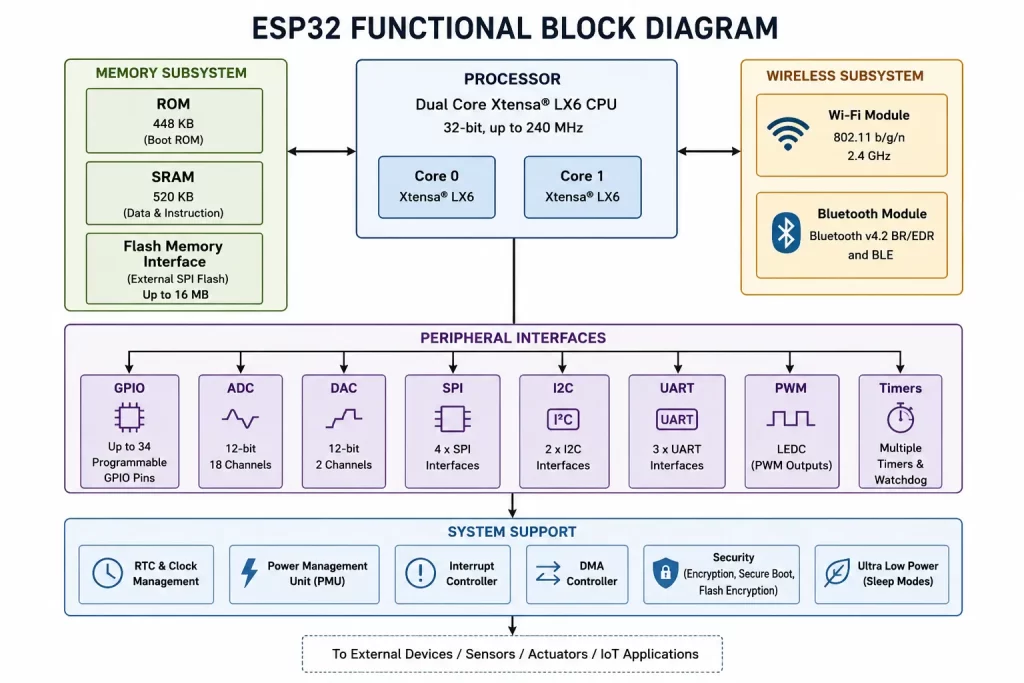
The ESP32 block diagram can be divided into five major sections:
1. Processing Unit
Responsible for executing firmware instructions.
2. Memory System
Stores program code, variables, and temporary data.
3. Wireless Communication System
Provides Wi-Fi and Bluetooth connectivity.
4. Peripheral Interfaces
Enables communication with sensors, displays, motors, and external devices.
5. Power Management System
Optimizes energy consumption for battery-powered applications.
Understanding these sections makes it easier to design efficient embedded systems and troubleshoot hardware issues.
Dual-Core Xtensa LX6 Processor
One of the most important components of the ESP32 architecture is its dual-core microcontroller design.
The ESP32 uses two Xtensa LX6 processors that can run simultaneously. This dual-core architecture allows the chip to handle multiple tasks efficiently without affecting overall performance.
For example:
- Core 0 can manage Wi-Fi communication.
- Core 1 can execute application logic.
This separation improves system responsiveness and reduces processing delays.
Advantages of Dual-Core Processing
Better Multitasking
Multiple operations can run at the same time.
Faster Execution
Tasks are distributed across both CPU cores.
Improved Real-Time Performance
Critical operations receive processor resources without interruption.
Efficient Wireless Handling
Wi-Fi and Bluetooth operations do not significantly affect application performance.
The processor can operate at clock frequencies up to 240 MHz, making it suitable for demanding IoT applications.
ESP32 Memory Architecture
Memory plays a critical role in any embedded system. The ESP32 memory architecture is designed to support both program execution and data storage.
The memory system consists of:
- ROM Memory
- SRAM Memory
- External Flash Memory
ROM Memory
ROM (Read-Only Memory) contains firmware and bootloader code permanently programmed by the manufacturer.
Functions of ROM memory include:
- Initial boot process
- Hardware initialization
- System diagnostics
- Firmware loading
ROM memory remains unchanged during normal operation.
SRAM Memory
SRAM (Static Random Access Memory) stores temporary data during execution.
Examples include:
- Variables
- Buffers
- Stack memory
- Heap memory
- Communication data
The ESP32 contains multiple SRAM blocks to improve processing efficiency and data access speed.
Because SRAM is volatile, its contents are lost when power is removed.
Flash Memory
Flash memory stores application firmware permanently.
It contains:
- User programs
- Configuration files
- Wireless settings
- OTA firmware updates
- File systems
The ESP32 typically works with external flash memory connected through a high-speed SPI interface.
Benefits include:
- Non-volatile storage
- Firmware upgrade capability
- Large storage capacity
Wi-Fi Module in ESP32
A major reason for ESP32‘s popularity is its integrated Wi-Fi module.
The built-in Wi-Fi hardware supports:
- 802.11 b/g/n standards
- Station Mode
- Access Point Mode
- Dual Operation Mode
This enables ESP32 devices to:
- Connect to routers
- Send sensor data to cloud platforms
- Host web servers
- Communicate with mobile applications
Because Wi-Fi is integrated into the chip, developers do not require additional wireless modules.
Bluetooth Module
The ESP32 also includes an integrated Bluetooth module.
Supported technologies include:
- Bluetooth Classic
- Bluetooth Low Energy (BLE)
Bluetooth functionality allows communication with:
- Smartphones
- Smartwatches
- Medical devices
- Industrial sensors
- Wearable electronics
BLE is especially useful for battery-powered IoT devices because it consumes significantly less power than traditional Bluetooth communication.
GPIO Pins in ESP32
GPIO (General Purpose Input Output) pins are among the most frequently used components in the ESP32 architecture. These pins allow the microcontroller to interact with external hardware devices such as sensors, LEDs, relays, displays, motors, and communication modules.
Unlike many traditional microcontrollers, ESP32 GPIO pins are highly flexible. Most pins can perform multiple functions depending on software configuration.
Common GPIO applications include:
- Reading sensor inputs
- Controlling LEDs
- Driving relays
- Interfacing with LCD displays
- Monitoring switches and buttons
- Communicating with external devices
The availability of numerous GPIO pins makes ESP32 suitable for complex embedded systems that require multiple peripherals.
Key Features of ESP32 GPIO Pins
Programmable Functionality
Most GPIO pins can be configured as:
- Digital Input
- Digital Output
- Interrupt Input
- Communication Interface Pins
Internal Pull-Up and Pull-Down Resistors
ESP32 includes internal resistors that simplify circuit design and reduce external components.
Interrupt Support
GPIO interrupts allow the processor to respond immediately to external events without continuously polling inputs.
ADC and DAC in ESP32
One of the major advantages of the ESP32 microcontroller block diagram is the integration of both Analog-to-Digital Converters (ADC) and Digital-to-Analog Converters (DAC).
This capability allows the ESP32 to work directly with analog sensors and analog output devices.
Analog-to-Digital Converter (ADC)
Many sensors generate analog voltage signals. Since processors operate digitally, these signals must be converted into digital values.
The ADC module performs this conversion.
Typical ADC applications include:
- Temperature sensors
- Light sensors
- Gas sensors
- Potentiometers
- Battery voltage monitoring
Benefits of ADC
- Enables sensor interfacing
- Eliminates external ADC chips in many projects
- Supports IoT data acquisition systems
Digital-to-Analog Converter (DAC)
The DAC converts digital values into analog voltages.
Applications include:
- Audio generation
- Signal generation
- Analog control systems
- Waveform creation
The presence of built-in DAC channels reduces the need for additional external components.
SPI Interface in ESP32
SPI (Serial Peripheral Interface) is a high-speed communication protocol widely used in embedded systems.
The SPI interface enables communication between the ESP32 and external devices such as:
- Displays
- Flash memory
- SD cards
- Sensors
- Wireless modules
SPI communication uses dedicated lines for:
- Clock signal
- Data transmission
- Data reception
- Device selection
Advantages of SPI Communication
High Speed
SPI is significantly faster than many other communication protocols.
Full-Duplex Operation
Data can be transmitted and received simultaneously.
Low Communication Overhead
This improves overall system performance.
Because of these benefits, SPI is commonly used in applications requiring fast data transfer.
I2C Communication Interface
I2C (Inter-Integrated Circuit) is another important communication peripheral in the ESP32 architecture.
Unlike SPI, I2C requires only two wires:
- SDA (Data Line)
- SCL (Clock Line)
Multiple devices can share the same communication bus.
Applications of I2C Communication
- Temperature sensors
- OLED displays
- RTC modules
- EEPROM memory devices
- Environmental sensors
Why I2C is Popular
- Simple wiring
- Reduced pin usage
- Easy integration of multiple devices
- Cost-effective hardware design
Many IoT projects rely heavily on I2C communication because of its simplicity and flexibility.
UART Communication
UART (Universal Asynchronous Receiver Transmitter) is one of the most widely used serial communication interfaces in embedded systems.
ESP32 supports multiple UART channels that enable communication with:
- Computers
- GPS modules
- GSM modules
- Industrial controllers
- Other microcontrollers
Functions of UART
Firmware Uploading
Most ESP32 boards use UART during programming.
Serial Monitoring
Developers can view debugging information through a serial terminal.
Device Communication
UART enables reliable point-to-point communication between electronic devices.
Because of its simplicity, UART remains one of the most important debugging and communication tools in embedded systems development.
PWM Generation in ESP32
PWM (Pulse Width Modulation) is a technique used to generate variable output signals.
The ESP32 contains dedicated PWM generation hardware capable of controlling numerous devices.
Applications of PWM
Motor Speed Control
PWM allows precise adjustment of DC motor speed.
LED Brightness Control
Changing duty cycle adjusts LED intensity.
Servo Motor Positioning
PWM signals determine servo angle.
Power Control Systems
Used in converters and switching circuits.
The advanced PWM hardware available in ESP32 makes it suitable for robotics, automation, and industrial applications.
Power Management Unit (PMU)
Power consumption is a critical factor in modern IoT development.
The ESP32 includes a sophisticated Power Management Unit that helps optimize energy usage.
The PMU manages:
- Processor power states
- Peripheral activation
- Wireless subsystem operation
- Sleep modes
ESP32 Sleep Modes
Active Mode
All hardware blocks remain operational.
Modem Sleep
Wireless modules are temporarily disabled.
Light Sleep
Processor activity is reduced while maintaining responsiveness.
Deep Sleep
Most hardware blocks are powered down, resulting in extremely low power consumption.
These power-saving features make ESP32 ideal for battery-powered devices.
Security Features in ESP32 Architecture
Security is becoming increasingly important in connected devices.
The ESP32 architecture incorporates multiple hardware security features.
Secure Boot
Prevents execution of unauthorized firmware.
Flash Encryption
Protects stored program code and sensitive information.
Cryptographic Acceleration
Dedicated hardware accelerates encryption algorithms.
Random Number Generator
Supports secure authentication and encryption mechanisms.
These security capabilities help developers build reliable IoT products that protect user data and communications.
How All ESP32 Components Work Together
When an ESP32-based device starts operating, multiple hardware blocks collaborate seamlessly.
For example, in a smart weather monitoring system:
- ADC reads sensor voltages.
- CPU processes sensor data.
- SRAM temporarily stores measurements.
- Wi-Fi module connects to the internet.
- Data is transmitted to a cloud platform.
- Flash memory stores configuration settings.
- PMU manages power consumption.
This integration of processing, memory, communication, and power management makes ESP32 a powerful embedded systems platform.

Applications of ESP32 in IoT Development
Because of its rich hardware architecture, ESP32 is widely used in various industries.
Smart Home Automation
- Smart switches
- Smart lighting
- Energy monitoring
Industrial Automation
- Machine monitoring
- Predictive maintenance
- Remote diagnostics
Healthcare Devices
- Wearable monitoring systems
- Health tracking sensors
Agriculture
- Soil moisture monitoring
- Irrigation control
- Environmental sensing
Consumer Electronics
- Wireless speakers
- Smart appliances
- IoT gadgets
Its combination of wireless communication, processing capability, and low power consumption makes ESP32 one of the most versatile microcontrollers available today.
Advantages of ESP32 Architecture
The ESP32 block diagram reveals several strengths that contribute to its popularity.
Integrated Wi-Fi and Bluetooth
No external wireless modules are required.
Dual-Core Processing
Improves multitasking and system performance.
Rich Peripheral Support
Supports SPI, I2C, UART, ADC, DAC, PWM, and GPIO.
Low Power Operation
Suitable for battery-powered applications.
Strong Security Features
Protects firmware and communication data.
Cost-Effective Solution
Provides advanced functionality at an affordable price.
These advantages explain why ESP32 is widely adopted in both educational and industrial embedded systems projects.
Conclusion
Understanding the ESP32 block diagram is essential for anyone working with embedded systems and IoT development. The architecture combines a powerful dual-core Xtensa LX6 processor, an efficient memory system, integrated Wi-Fi and Bluetooth modules, versatile communication interfaces, ADC and DAC capabilities, advanced PWM generation, and robust power management features within a single chip.
By understanding how each block functions and interacts with other components, developers can design more efficient, reliable, and scalable embedded applications. Whether you are building a simple sensor node or a complex industrial IoT system, knowledge of the ESP32 architecture provides the foundation needed to fully utilize the capabilities of this powerful microcontroller.