What Is OBD-II in Vehicles?
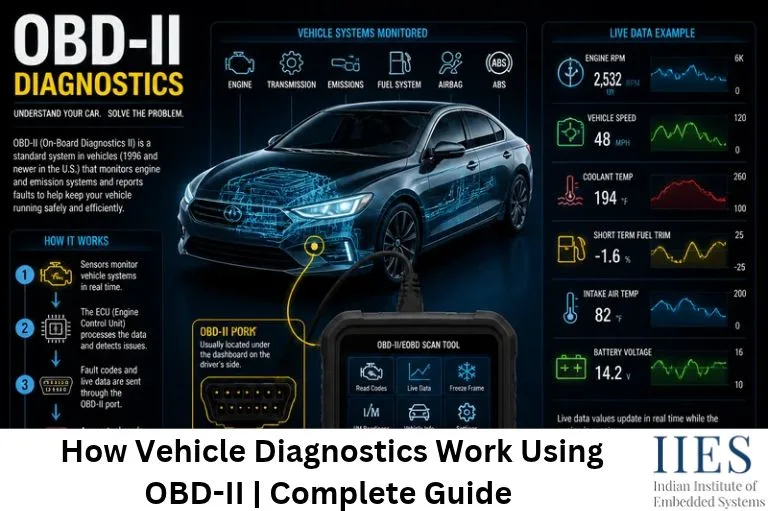
OBD-II (On-Board Diagnostics II) is an automotive diagnostic standard designed to monitor vehicle performance and detect malfunctions, particularly those related to engine operation and emissions control.
It provides a standardized diagnostic interface through which external scanning devices can access information stored in the vehicle’s Engine Control Unit (ECU).
The OBD-II system monitors several parameters, including:
- Engine temperature
- Vehicle speed
- Engine RPM
- Oxygen sensor readings
- Fuel system performance
- Throttle position
- Emission control system
- Air intake temperature
When the system detects an abnormal condition, it can generate a Diagnostic Trouble Code (DTC) and activate the Check Engine Light, depending on the fault and its severity.
How Does OBD2 Vehicle Diagnostics Work?
The OBD-II diagnostic system works by collecting information from different sensors installed throughout the vehicle. These sensors continuously send signals to the ECU, which processes the information and checks whether the vehicle is operating within predefined parameters.
The diagnostic process generally involves the following steps:
Sensor Data Collection
Modern vehicles contain multiple sensors that monitor different operating conditions. These sensors collect real-time information and send electrical signals to the ECU.
Examples include:
- Oxygen Sensors: Monitor the oxygen content in exhaust gases.
- Coolant Temperature Sensors: Measure engine temperature.
- Mass Air Flow (MAF) Sensors: Measure incoming air.
- Throttle Position Sensors (TPS): Monitor throttle opening.
- Crankshaft Position Sensors: Monitor engine rotational position and speed.
The ECU uses this information to control engine functions and identify abnormal operating conditions.
ECU Data Processing
The ECU receives sensor signals and processes them using its internal software and control algorithms. It compares the collected information with predefined operating limits and diagnostic conditions.
If a parameter goes outside its expected range or a monitored system fails its diagnostic test, the ECU may register a fault.
Fault Detection and Diagnostic Trouble Codes
When the ECU identifies a malfunction, it can store a Diagnostic Trouble Code (DTC). These codes help technicians understand which system or component may be experiencing a problem.
Communication Through the OBD-II Port
Every OBD-II-compliant vehicle provides a standardized 16-pin diagnostic connector, generally located near the driver’s dashboard. A diagnostic scanner connects to this port and communicates with the ECU.
The scanner sends diagnostic requests, and the ECU responds with information such as:
- Stored diagnostic trouble codes
- Pending fault codes
- Engine RPM and vehicle speed
- Coolant temperature
- Fuel system status
- Sensor readings
Fault Analysis and Troubleshooting
After retrieving diagnostic information, technicians analyze the trouble codes and live sensor readings to identify the possible source of the problem.
For example, if a scanner displays a P0300 code, the technician may investigate spark plugs, ignition coils, fuel delivery, or other engine-related components. A diagnostic code does not always identify the exact defective component, so additional testing is necessary to confirm the root cause.

Role of Embedded Systems in OBD2 Vehicle Diagnostics
Embedded systems are fundamental to modern OBD-II diagnostics. The diagnostic functionality depends on microcontrollers, sensors, ECUs, communication interfaces, and embedded software.
Let’s understand the major roles of embedded technology in OBD2.
Microcontroller-Based ECU Control
A microcontroller acts as the processing unit of the ECU. It receives sensor signals, executes diagnostic routines, identifies abnormal conditions, and stores relevant fault information.
Automotive-grade microcontrollers are designed to handle real-time operations and safety-related tasks.
Sensor Data Processing
The embedded controller processes information from different sensors to understand engine operating conditions. Accurate sensor processing helps the system detect faults reliably and avoid false alarms.
CAN Communication in OBD2
Modern vehicles contain multiple Electronic Control Units that communicate with each other. CAN (Controller Area Network) allows diagnostic scanners to retrieve information from compatible vehicle control modules. Embedded software manages this communication and processes diagnostic requests according to the protocol.
Fault Storage and Diagnostics
When a fault is confirmed, the embedded software stores the Diagnostic Trouble Code, can save freeze-frame data, and activates the Check Engine Light when required.
Real-Time Software
Diagnostic routines must run alongside engine control tasks without disturbing real-time operation. This makes real-time embedded software a key part of ECU development.
Embedded systems engineers working in automotive development should understand:
- Microcontroller architecture
- Automotive sensor interfacing
- CAN communication
- UART and serial communication
- ECU programming
- Diagnostic protocols
- Real-time embedded software
- Automotive testing and debugging
What Are OBD2 Diagnostic Trouble Codes?
OBD2 Diagnostic Trouble Codes are standardized codes used to identify malfunctions detected by the vehicle’s onboard diagnostic system. Most standardized DTCs contain five characters.
The first character identifies the system category:
| First Character | System Category |
| P | Powertrain (engine and transmission) |
| B | Body |
| C | Chassis |
| U | Network and communication |
The remaining characters provide information about the specific fault category and condition. For example, P0301 indicates a cylinder 1 misfire. Some common examples are shown below.
| DTC | Description |
| P0300 | Random or multiple cylinder misfire detected |
| P0171 | System too lean (Bank 1) |
| P0420 | Catalyst system efficiency below threshold (Bank 1) |
| P0115 | Engine coolant temperature sensor circuit malfunction |
| P0101 | Mass or volume air flow circuit range/performance problem |
These codes provide an initial indication of the issue and help technicians perform further investigation.
OBD2 Communication Protocols Used in Automotive Diagnostics
OBD2 communication protocols define how diagnostic scanners exchange information with vehicle electronic control units. Different vehicles may support different protocols depending on their manufacturing period, design, and region.
| Protocol | Description |
| SAE J1850 PWM | Uses Pulse Width Modulation; commonly used in certain older vehicles, particularly Ford models |
| SAE J1850 VPW | Uses Variable Pulse Width; commonly associated with certain General Motors vehicles |
| ISO 9141-2 | Serial communication protocol widely used in several older European and Asian vehicles |
| ISO 14230-4 (KWP2000) | Supports retrieval of diagnostic information and certain diagnostic operations |
| ISO 15765-4 (CAN) | Widely used in modern vehicles; lets multiple ECUs exchange information over a shared network |
Role of CAN Bus in Automotive Diagnostics
A vehicle may contain multiple ECUs responsible for engine control, transmission, braking, airbags, and other functions. Instead of separate wiring between every module, the CAN bus allows multiple ECUs to communicate over a shared network.
The CAN bus generally uses two communication lines:
- CAN High (CAN-H)
- CAN Low (CAN-L)
These lines carry differential signals that improve communication reliability in electrically noisy automotive environments. CAN bus plays an important role in real-time data exchange, ECU communication, and fault diagnosis.

What Is an OBD2 Scanner and How Does It Work?
An OBD2 scanner is an electronic diagnostic device that communicates with a vehicle’s ECU through the OBD-II diagnostic connector. It retrieves fault codes, displays live sensor information, and provides data about vehicle operating conditions.
The basic working process includes:
- Connect the scanner to the vehicle’s diagnostic port.
- Switch on the ignition or start the engine, depending on the scanner instructions.
- Establish communication with the ECU.
- Send diagnostic service requests.
- Receive fault codes and vehicle parameter data.
- Display the collected information for analysis.
Some advanced scanners also support clearing certain fault codes, monitoring sensor data, and viewing freeze-frame information.
Understanding OBD2 Live Data Monitoring
OBD2 live data monitoring allows technicians to observe vehicle operating parameters while the engine is running. Unlike stored trouble codes, live data provides continuously updated information about selected parameters.
| Parameter | Function |
| Engine RPM | Measures engine rotational speed |
| Vehicle Speed | Displays vehicle speed |
| Coolant Temperature | Monitors engine cooling temperature |
| Throttle Position | Indicates throttle opening |
| Intake Air Temperature | Measures incoming air temperature |
| Oxygen Sensor Voltage | Helps monitor exhaust oxygen levels |
| Mass Air Flow | Measures the amount of incoming air |
Analyzing these parameters helps technicians identify abnormal operating conditions and understand how different automotive components interact.
Difference Between OBD1 and OBD2
OBD1 and OBD2 are two generations of automotive onboard diagnostic systems. OBD2 improved diagnostic accessibility by introducing standardized requirements and communication methods.
| Feature | OBD1 | OBD2 |
| Standardization | Manufacturer-specific implementations | Standardized diagnostic requirements |
| Diagnostic Connector | Different connectors depending on manufacturer | Standardized 16-pin connector |
| Fault Codes | Manufacturer-specific codes | Standardized code structure |
| Communication | Manufacturer-dependent | Standardized protocols |
| Diagnostic Functions | Limited diagnostic capabilities | More comprehensive diagnostic functions |
| Vehicle Compatibility | Older vehicles | Generally vehicles from 1996 onward in the US, with regional differences |
Applications of OBD-II Vehicle Diagnostics
OBD-II vehicle diagnostics is used in several automotive applications.
Engine Performance Monitoring
OBD2 systems help monitor engine parameters, identify performance-related faults, and support troubleshooting.
Emission Control Monitoring
The diagnostic system monitors emission-related components to help identify failures that could increase vehicle emissions.
Vehicle Health Monitoring
Diagnostic scanners can retrieve fault information and selected operating parameters to help technicians assess vehicle condition.
Fleet Management Systems
OBD2 devices can collect vehicle information such as speed, engine RPM, and diagnostic trouble codes. When integrated with GPS and wireless connectivity, this information can support fleet monitoring and vehicle maintenance.
Predictive Vehicle Maintenance
OBD2 data can be used alongside additional sensor information and analytics systems to identify unusual operating patterns and support preventive maintenance planning.
Future of OBD2 and Automotive Diagnostics
Automotive diagnostics continues to evolve with connected vehicle technologies, advanced sensors, and intelligent data analysis. OBD2 data can be integrated with telematics devices, cloud platforms, and fleet management applications to support remote vehicle monitoring.
- Connected Vehicle Diagnostics: Wireless connectivity allows vehicle information to be transmitted to remote monitoring platforms.
- AI-Based Vehicle Fault Detection: Machine learning techniques can analyze vehicle operating data to identify unusual patterns and support fault prediction.
- Predictive Maintenance: Historical diagnostic information can be combined with real-time data to help identify potential maintenance requirements.
- Advanced Automotive Communication: Technologies such as CAN FD and Automotive Ethernet support the growing communication requirements of modern vehicles, alongside established diagnostic standards.
These developments are increasing the importance of embedded software, automotive networking, and vehicle data analytics.
Practical Example: Diagnosing a Misfire Using OBD2
Consider a vehicle whose Check Engine Light turns on while the driver is accelerating.
The following process takes place:
- The crankshaft position sensor and other sensors detect irregular engine behavior.
- The ECU compares the sensor data with its predefined limits.
- The misfire monitor confirms the fault and the ECU stores code P0300.
- The ECU activates the Check Engine Light.
- A technician connects an OBD2 scanner to the 16-pin port.
- The scanner sends a request over the CAN bus and the ECU returns the stored code.
- The technician checks live data and inspects spark plugs, ignition coils, and fuel delivery.
- After the repair, the fault is cleared and the vehicle is re-tested.
For engineering students, this example demonstrates how sensors, ECUs, CAN communication, embedded C programming, and diagnostic protocols work together in a practical automotive application.
Skills Required to Develop Automotive Diagnostic Systems
Developing OBD2 and diagnostic features requires knowledge of both hardware and software.
Some important technical skills include:
- Embedded C programming
- Microcontroller architecture
- Sensor interfacing
- CAN communication protocol
- UART and serial communication
- Diagnostic protocols and DTC handling
- ECU development and testing
- Real-time operating systems (RTOS)
- Automotive testing and debugging
These skills are useful for engineers interested in automotive embedded development, ECU programming, vehicle electronics, and automotive diagnostics.
Career Opportunities in Automotive Diagnostics and Embedded Systems
The increasing use of ECUs and connected-vehicle technology is creating opportunities for engineers with automotive embedded systems knowledge.
Some relevant job roles include:
| Job Role | Major Responsibilities |
| Embedded Software Engineer | Develops embedded software for automotive controllers |
| Automotive Embedded Engineer | Works on vehicle electronic systems |
| ECU Developer | Develops and tests ECU and diagnostic software |
| Diagnostics Engineer | Implements and validates diagnostic services and fault codes |
| Automotive Testing Engineer | Performs ECU validation and functional testing |
| Telematics Engineer | Works on connected vehicle and fleet monitoring systems |
Knowledge of embedded C, microcontrollers, CAN communication, and automotive electronics can help engineering graduates prepare for these technical roles.
Conclusion
OBD-II vehicle diagnostics plays an important role in modern automotive systems by enabling standardized communication between diagnostic tools and vehicle ECUs.
From collecting sensor information and processing ECU data to identifying diagnostic trouble codes and monitoring live parameters, OBD2 makes vehicle troubleshooting more systematic and accessible.
Understanding OBD2 communication protocols, CAN bus technology, embedded controllers, and automotive sensors provides a strong foundation for anyone interested in automotive embedded systems. As vehicles become more connected and software-driven, this knowledge will continue to be valuable for engineers in the automotive industry.
For electronics and engineering graduates interested in automotive technology, understanding OBD2 provides practical insight into how embedded systems are used in real-world vehicle applications.
Learning these technologies through practical projects and hands-on training can help students build the technical foundation required for careers in automotive embedded systems.