Importance of Communication Protocols in Microcontroller Systems
In embedded systems, communication protocols determine how microcontrollers exchange data with peripherals and controllers. They influence:
- Data transfer speed
- Number of connected devices
- Error detection and recovery
- System reliability in noisy environments
An incorrect protocol choice can cause data corruption, timing failures, EMI issues, and poor scalability. Understanding embedded communication protocols is essential for robust system design.
SPI Communication Protocol in Microcontrollers
SPI (Serial Peripheral Interface) is a synchronous, full-duplex protocol used for high-speed, short-distance data transfer.
SPI Architecture and Signal Lines
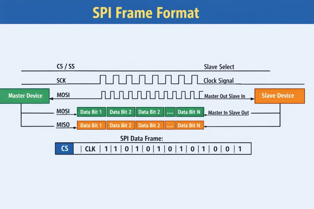
- MOSI – Master Out Slave In
- MISO – Master In Slave Out
- SCK – Serial Clock
- SS / CS – Slave Select / Chip Select
SPI Data Transmission Mechanism
- Master and slave use shift registers
- Data is transmitted and received simultaneously
- Common word lengths are 8-bit or 16-bit
SPI Timing Modes (CPOL / CPHA)
SPI supports four timing modes defined by Clock Polarity (CPOL) and Clock Phase (CPHA).
Advantages of SPI
- Very high data rates (tens of Mbps)
- Full-duplex communication
- Low latency
Disadvantages of SPI
- More GPIO pins required
- No built-in addressing or error checking
- Short communication distance
Typical SPI Use Cases
- SD cards, Flash memory
- Displays, ADCs, DACs
- Camera modules

I²C Communication Protocol in Microcontrollers
I²C (Inter-Integrated Circuit) is a two-wire, half-duplex protocol for low-speed peripheral communication.
I²C Architecture and Signal Lines
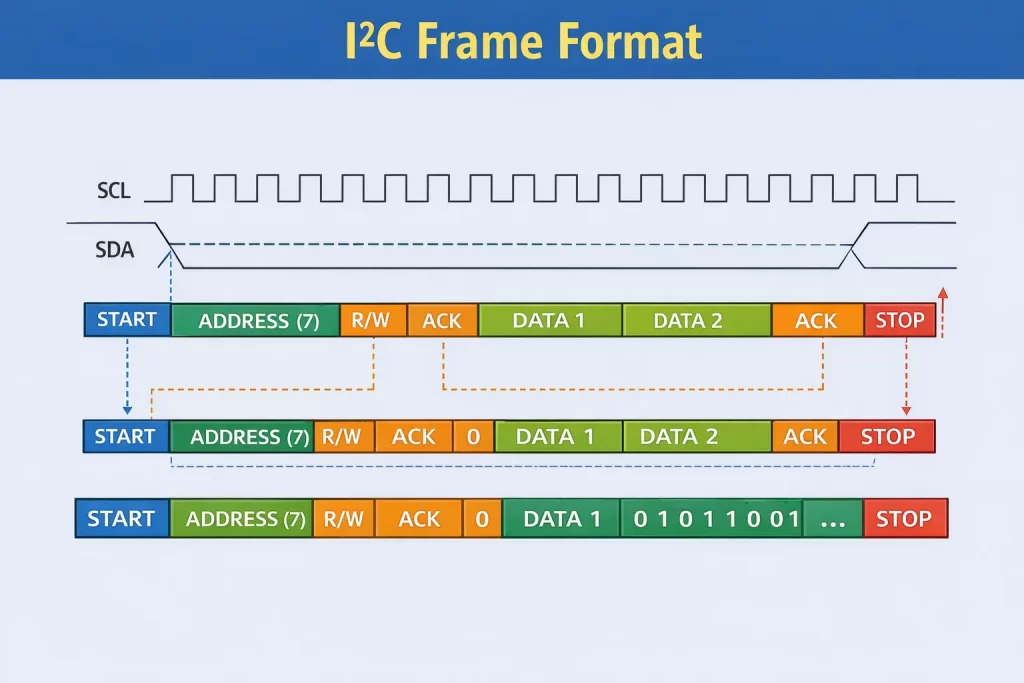
- SDA – Serial Data
- SCL – Serial Clock
Addressing and Bus Conditions
- 7-bit and 10-bit addressing
- START and STOP conditions
- ACK / NACK after every byte
I²C Frame Format
START → Address + R/W → ACK → Data → ACK → STOP
Advantages of I²C
- Only two wires required
- Built-in addressing
- Low hardware cost
Limitations of I²C
- Slower (100 kHz – 3.4 MHz)
- Limited distance (< 1 m)
- Pull-ups limit scalability
Typical I²C Use Cases
- Sensors, EEPROM, RTC
- Power-management ICs
CAN Communication Protocol in Embedded Systems
CAN (Controller Area Network) is a multi-master, message-based protocol for noisy environments.
CAN Architecture and Signaling
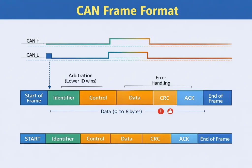
- Differential signaling (CAN_H, CAN_L)
- Uses message identifiers instead of addresses
- External CAN transceivers required
CAN Frame Format
- Start of Frame
- Identifier (11 / 29-bit)
- Control Field
- Data Field
- CRC
- ACK
- End of Frame
Arbitration and Error Handling
- Priority arbitration (lower ID = higher priority)
- Automatic retransmission
- Error-passive and bus-off states
Advantages of CAN
- High reliability
- Excellent noise immunity
- Long distance (up to ~1 km)
Limitations of CAN
- More complex protocol
- Extra hardware required
- Lower speed than SPI

SPI vs I²C vs CAN Comparison
| Feature | SPI | I²C | CAN |
|---|
| Type | Full-duplex | Half-duplex | Differential |
| Wires | 4+ | 2 | 2 |
| Speed | ~50 Mbps | 3.4 Mbps | 1–5 Mbps |
| Distance | Short | Short | Long |
| Error Handling | None | ACK/NACK | CRC + Retransmission |
How to Choose the Right Communication Protocol
Choose SPI if:
- High data throughput is required
- Low latency is critical
- Devices are close to the microcontroller
Choose I2C if:
- Multiple low-speed devices share a bus
- Minimal wiring is required
- Communication is non-critical
Choose CAN if:
- Reliability is more important than speed
- Long cable lengths are involved
- The environment is noisy or safety-critical
Quick rule:
Speed → SPI
Simplicity → I2C
Reliability → CAN
Standards, Specifications, and Compliance References
The communication protocols discussed are governed or influenced by internationally recognized standards:
- SPI: Widely adopted de-facto standard implemented consistently by manufacturers such as Microchip, STMicroelectronics, NXP, and Texas Instruments.
- I²C: Officially specified and maintained by NXP Semiconductors, defining electrical, timing, and addressing requirements.
- CAN: Standardized under the ISO 11898 family of standards and originally developed by Bosch, making it suitable for automotive and industrial systems worldwide.
Designing according to these specifications ensures interoperability, robustness, and long-term reliability.
Real-World Usage Examples
- SPI: Displays, SD cards, ADCs
- I2C: Sensors, EEPROMs, RTCs
- CAN: Automotive ECUs, industrial controllers
Conclusion
There is no single communication protocol that fits all embedded applications.
- SPI is ideal for high-speed data transfer
- I²C is best for simple, low-cost peripheral connections
- CAN excels in reliable, long-distance, and safety-critical systems
A solid understanding of SPI, I2C, and CAN communication protocols enables engineers to design efficient, scalable, and reliable embedded systems.