Basics of UART Communication
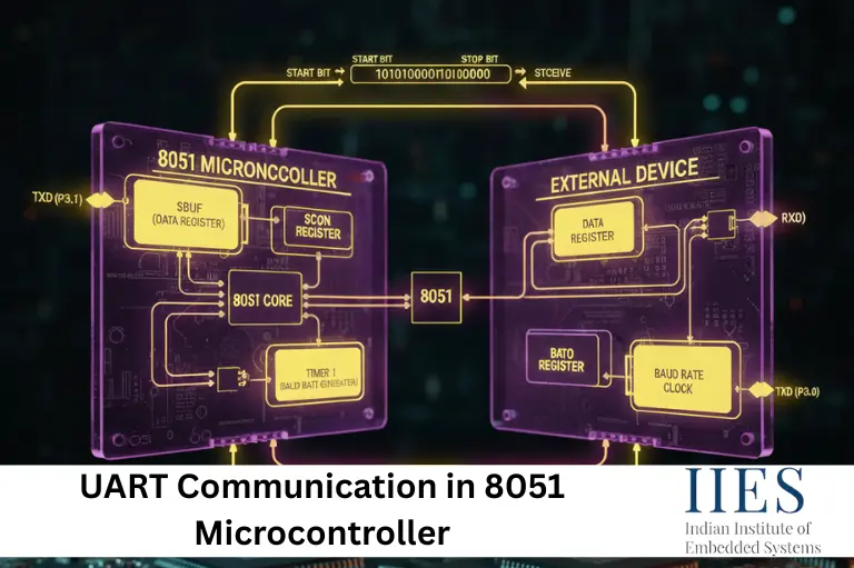
UART (Universal Asynchronous Receiver/Transmitter) communication is an asynchronous serial data transmission technique. Since it is asynchronous, no clock signal is shared between the transmitter and receiver.
How UART Works
- No clock line required
- Uses TX (Transmit) and RX (Receive) pins
- UART pins in 8051:
- Data format:
- 1 Start bit
- 8 Data bits
- 1 Stop bit
- Communication speed is determined by the baud rate
UART vs SPI vs I2C
| Feature | UART | SPI | I2C |
|---|
| Type | Asynchronous | Synchronous | Synchronous |
| Pins | TX, RX | MOSI, MISO, SCK, SS | SDA, SCL |
| Speed | Moderate | High | Moderate |
| Devices | Point-to-Point | Multi-Slave | Multi-Master |
Registers Used in UART Communication in 8051
UART operation in the 8051 microcontroller is controlled using three important registers.
1. SCON Register in 8051
The SCON (Serial Control) register is used to select the UART mode and control transmission and reception.
| Bit | Name | Function |
|---|
| SM0, SM1 | Mode Select | Selects UART mode |
| REN | Receive Enable | Enables reception |
| TI | Transmit Interrupt | Set after transmission |
| RI | Receive Interrupt | Set after reception |
2. PCON Register
The PCON register controls power and baud rate.
SMOD bit doubles the baud rate when set.
3. SBUF Register in 8051
The SBUF (Serial Buffer) register stores:
- Data to be transmitted
- Data received via UART
UART Modes in 8051 Microcontroller
The 8051 supports four UART modes.
| Mode | Description | Baud Rate |
|---|
| 0 | Shift Register Mode | Fixed |
| 1 | 8-bit UART | Variable |
| 2 | 9-bit UART | Fixed |
| 3 | 9-bit UART | Variable |
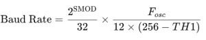
Baud Rate Calculation in 8051 UART
- The baud rate in 8051 UART communication is generated using Timer 1
- Timer 1 is configured in Mode 2 (8-bit auto-reload)
- Used in UART Mode 1 and Mode 3
- Common crystal frequency: 11.0592 MHz
- This ensures accurate baud rates such as 9600, 4800, 2400 bps, etc.
UART Programming Steps in 8051
Follow these steps to implement UART communication:
- Configure Timer 1 in Mode 2
- Load baud rate value into TH1
- Configure UART mode using SCON register
- Enable serial reception
- Load data into SBUF
- Monitor TI and RI flags
Practical UART Communication Examples
GSM Module Interfacing with 8051 (SMS Sending)
Concept:
GSM modules such as SIM800/SIM900 communicate using AT commands via UART.
Connections:
| GSM Module | 8051 |
|---|
| TXD | P3.0 (RXD) |
| RXD | P3.1 (TXD) |
| GND | GND |
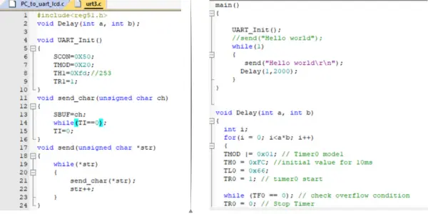
Sample UART C Code (Send SMS):
#include

void uart_init(){
    TMOD = 0x20;
    TH1 = 0xFD;     // 9600 baud @ 11.0592MHz
    SCON = 0x50;
    TR1 = 1;
}

void uart_tx(char ch){
    SBUF = ch;
    while(TI==0);
    TI = 0;
}

void uart_string(char *s){
    while(*s)
        uart_tx(*s++);
}

void main(){
    uart_init();
    uart_string("AT\r\n");
    uart_string("AT+CMGF=1\r\n");
    uart_string("AT+CMGS=\"+919xxxxxxxxx\"\r\n");
    uart_string("Hello from 8051");
    uart_tx(0x1A);   // CTRL+Z
    while(1);
}
Bluetooth HC-05 Interfacing with 8051
Concept:
HC-05 works as a wireless serial cable.
char rx;

void main(){
    uart_init();
    while(1){
        while(RI==0);
        rx = SBUF;
        RI = 0;
        uart_tx(rx);   // Echo received data
    }
}
GPS Module Interfacing with 8051
Concept:
GPS modules continuously send NMEA sentences via UART.
char gps;

void main(){
    uart_init();
    while(1){
        while(RI==0);
        gps = SBUF;
        RI = 0;
        uart_tx(gps);
    }
}
PC-Based Monitoring System
Concept:
Sensor values are transmitted to a PC for real-time monitoring.
void main(){
    uart_init();
    while(1){
        uart_string("Temp = 30C\r\n");
    }
}
Sensor Data Logging with SD Card
Concept:
Sensor data is transmitted to an SD card module via UART-SPI converter.
void main(){
    uart_init();
    while(1){
        uart_string("Sensor Value: 123\r\n");
    }
}
Applications of UART Communication
UART communication in 8051 is used in:
- GSM-based projects
- Bluetooth communication
- GPS tracking systems
- Industrial monitoring
- IoT and data logging systems
Conclusion
UART communication in 8051 microcontroller is a fundamental concept in embedded systems. By correctly configuring UART registers and baud rate timing, reliable serial communication can be achieved with real-world devices. Mastering UART makes it easier to work with advanced protocols such as SPI, I2C, and modern microcontrollers.