What is an Embedded System?
An embedded system is a combination of hardware and software designed to perform a dedicated function within a larger system.
Unlike general-purpose computers, embedded systems are optimized for:
- Specific tasks
- Low power consumption
- High reliability
- Real-time operation
Examples
- Washing machine controller
- ATM machine
- Smart thermostat
- Car engine control unit (ECU)

What is the Block Diagram of an Embedded System?
The block diagram of an embedded system is a graphical representation that shows:
- Main components of the system
- Data flow between blocks
- Input–process–output relationship
- Control mechanism
It helps students and engineers understand system design, debugging, and troubleshooting.
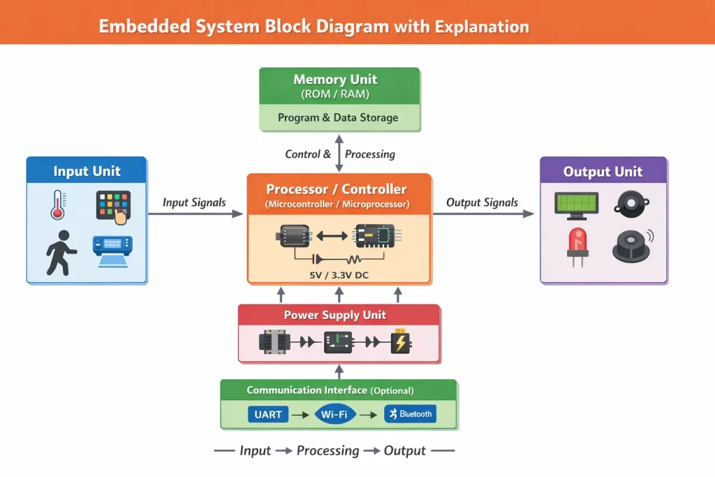
Basic Block Diagram of Embedded System
Recommended Image Title: Embedded System Block Diagram with Explanation
Alt Text: embedded system block diagram showing input processor memory output power supply
General Structure
A basic embedded system consists of the following blocks:
- Input Unit
- Processor (Controller)
- Memory Unit
- Output Unit
- Power Supply Unit
- Communication Interface (Optional)
Explanation of Each Block
1. Input Unit
The input unit collects data from the external environment and sends it to the processor.
Functions
- Converts physical signals into electrical signals
- Sends sensor data to the controller
Examples
- Temperature sensor
- Keypad
- Push button
- Light sensor
- Pressure sensor
Example:
In a temperature monitoring system, the temperature sensor sends temperature data to the controller.
2. Processor (Controller Unit)
The processor is the brain of the embedded system. It controls all operations and executes the program.
Types
Microcontroller
CPU + Memory + I/O on one chip
Most commonly used
Microprocessor
Only CPU
Requires external components
Functions
- Reads input data
- Executes instructions
- Controls output devices
Examples
- Arduino
- PIC microcontroller
- ARM controller
3. Memory Unit
The memory unit stores programs and data required for system operation.
Types of Memory
a) Program Memory (ROM / Flash)
Stores firmware
Non-volatile
b) Data Memory (RAM)
Stores temporary data
Volatile
Functions
- Stores instructions
- Saves sensor readings
- Stores intermediate results
4. Output Unit
The output unit displays results or performs physical actions.
Functions
- Converts electrical signals into physical output
Examples
- LCD display
- LED
- Motor
- Buzzer
- Relay
Example:
In an automatic fan system, the motor turns ON/OFF based on temperature.
5. Power Supply Unit
The power supply provides the required voltage to all components.
Functions
- Converts AC to DC
- Regulates voltage
- Protects components
Components
- Transformer
- Rectifier
- Filter
- Voltage regulator
Example:
Most embedded systems operate on 5V or 3.3V DC supply.
6. Communication Interface (Optional)
This block enables data exchange between devices.
Functions
- Transfers data to external systems
Examples
- UART
- SPI
- I2C
- Wi-Fi
- Bluetooth
- GSM
Example:
IoT devices use Wi-Fi to send data to cloud servers.

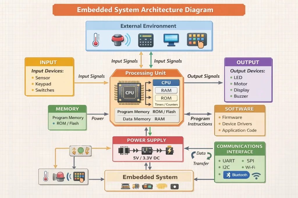
Embedded System Architecture Diagram
Recommended Image Title: Embedded System Architecture Diagram
Alt Text: embedded system architecture hardware software interaction diagram
The architecture shows how hardware and software work together efficiently.
Working of Embedded System (Step-by-Step)
Let us understand the working process:
Step 1: Data Collection
Input devices collect data from the environment.
Step 2: Data Processing
The controller reads input and executes the program.
Step 3: Decision Making
The processor compares input data with stored values.
Step 4: Output Generation
Output devices are activated based on decisions.
Step 5: Continuous Operation
The system works continuously in a loop.
Example: Automatic Temperature Control System
- Sensor measures temperature
- Controller reads sensor data
- Program checks limit
- Fan turns ON/OFF
- Process repeats
Examples of Embedded System Block Diagram
1. Washing Machine Controller
Input:
Buttons
Water level sensor
Controller:
Microcontroller
Output:
Motor
Display
Buzzer
Function:
Controls washing cycles automatically.
2. Smart Home System
Input:
Motion sensor
Light sensor
Controller:
Microcontroller
Output:
Lights
Fans
Alarms
Function:
Automates home appliances.
Characteristics of Embedded Systems
- Dedicated functionality
- Real-time operation
- Low power consumption
- Small size
- High reliability
- Cost-effective design
Advantages of Embedded System Block Diagram
- Easy to understand system structure
- Helps in learning electronics
- Useful for troubleshooting
- Improves hardware design
- Supports project development
Applications of Embedded Systems
Embedded systems are widely used in:
- Medical devices
- Automotive systems
- Industrial automation
- Consumer electronics
- IoT devices
- Telecommunication systems
Why Learn Embedded Systems at IIES?
At Indian Institute of Embedded System (IIES), students receive hands-on training in embedded systems, IoT, and automation using real-time industry projects.
Our training includes:
- Practical lab sessions
- Industry-oriented curriculum
- Placement support
- Project mentoring
- Expert faculty guidance
This helps students build strong technical and professional skills.
Conclusion
The block diagram of an embedded system is the foundation for understanding embedded technology. It explains how input devices, processor, memory, and output units work together to perform specific tasks. By learning the embedded system block diagram with explanation, students can easily design, analyze, and implement real-world projects. Understanding this concept is the first step. toward becoming a successful embedded systems engineer.