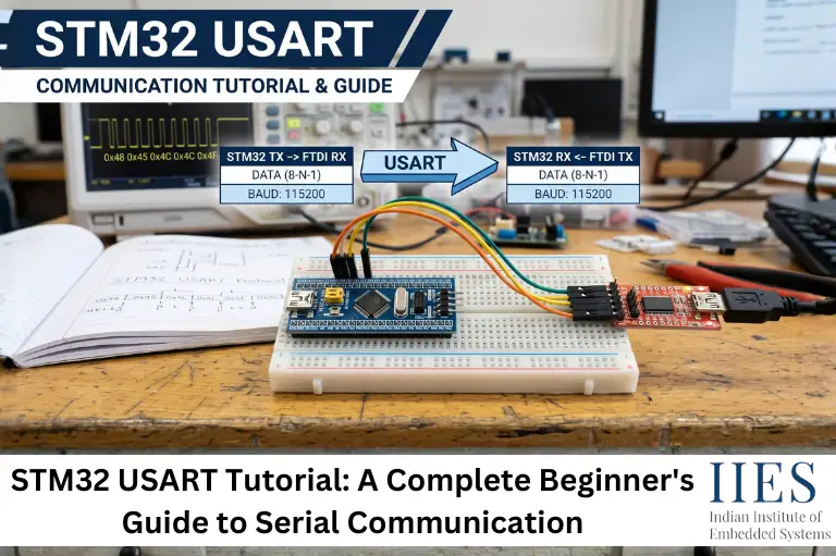
What is USART?
USART (Universal Synchronous Asynchronous Receiver Transmitter) is a hardware communication peripheral that enables serial data transfer between an STM32 microcontroller and external devices. Unlike UART, USART can operate in both synchronous and asynchronous communication modes.
Instead of sending multiple bits simultaneously, USART transmits data one bit at a time through dedicated communication lines. This reduces the number of required pins while maintaining reliable communication over short and medium distances.
Communication Modes
Asynchronous Communication
- Does not require a shared clock signal
- Uses TX (Transmit) and RX (Receive) pins
- Most commonly used communication mode
- Ideal for PC communication, Bluetooth, GPS, and sensors
Synchronous Communication
- Requires an additional clock signal
- Allows better synchronization between devices
- Suitable for applications requiring precise timing
- Less commonly used than asynchronous mode
Basic USART Communication Process
- Application sends data.
- USART converts parallel data into serial bits.
- Data is transmitted through the TX pin.
- Receiving device reads data through the RX pin.
- Received serial data is converted back into parallel format.
Because this entire process is handled by dedicated hardware, the CPU performs fewer communication-related tasks and can focus on application logic.

UART vs USART
Many beginners assume USART and UART are the same, but there is an important difference.
UART only supports asynchronous communication, whereas USART supports both synchronous and asynchronous communication. When operating in asynchronous mode, a USART functions exactly like a UART.
Feature | USART | UART |
Communication Mode | Synchronous and Asynchronous | Asynchronous Only |
Clock Signal | Optional | Not Required |
Data Lines | TX, RX, Optional Clock | TX and RX |
Communication Speed | Higher in synchronous mode | Suitable for most applications |
Hardware Complexity | Slightly Higher | Simpler |
Common Applications | Industrial systems, embedded devices, automotive | GPS, Bluetooth, PC communication |
Features of STM32 USART
STM32 microcontrollers include several hardware features that simplify serial communication while reducing CPU workload.
Full-Duplex Communication
- Send and receive data simultaneously
- Improves communication efficiency
- Suitable for continuous data exchange
Configurable Baud Rate
- Supports various communication speeds
- Common values include 9600, 115200, and 921600 bps
- Generated using the internal baud rate register
Programmable Frame Format
USART allows developers to configure:
- Data bits
- Stop bits
- Parity
- Communication speed
This flexibility helps match the communication settings of different external devices.
Interrupt Support
USART can generate interrupts whenever:
- Data is received
- Transmission is complete
- Errors occur
This enables responsive, non-blocking communication without constantly polling the peripheral.
DMA Support
Direct Memory Access (DMA) allows USART to transfer data between memory and the peripheral without continuous CPU involvement. This is particularly useful for high-speed communication or applications that handle large amounts of serial data.
Error Detection
STM32 USART hardware can detect several communication errors, including:
- Parity errors
- Framing errors
- Noise errors
- Overrun errors
These features help improve communication reliability and simplify debugging during firmware development.
How Does USART Work in STM32?
To understand STM32 USART programming, it’s helpful to know what happens internally when data is transmitted or received. Although the HAL library simplifies programming, the USART peripheral still follows a specific communication process.
USART converts parallel data from the CPU into serial data for transmission. At the receiving end, it converts the serial data back into parallel form so that the application can process it.
Basic Communication Flow
Application

     │

     ▼

STM32 CPU

     │

     ▼

USART Peripheral

     │

     ▼

TX Pin ─────────────► RX Pin

                    External Device
How Data is Transmitted
When an application sends a character:
- The CPU writes data to the USART transmit register.
- The USART converts the byte into a serial frame.
- The frame is transmitted through the TX pin.
- The receiving device reconstructs the original byte.
How Data is Received
When data arrives:
- The USART detects the start bit.
- Each data bit is sampled according to the configured baud rate.
- The received byte is stored in the receive register.
- The application reads the data using the HAL library or directly from the register.
Understanding a USART Data Frame
Every transmitted byte follows a predefined frame format.
| Start | Data Bits | Optional Parity | Stop |
| 1 Bit | 8/9 Bits | 1 Bit |1/2 Bit|
Start Bit
- Indicates the beginning of communication.
- Always transmitted first.
- Synchronizes the receiver.
Data Bits
- Usually 8 bits.
- Some applications use 9-bit communication.
- Represents the actual information being sent.
Parity Bit
- Optional error-checking bit.
- Can be:
- Even parity
- Odd parity
- No parity
Stop Bit
- Indicates the end of a frame.
- Can be:
- 1 Stop Bit
- 0.5 Stop Bit
- 1.5 Stop Bits
- 2 Stop Bits
Baud Rate
The baud rate defines how fast data is transmitted.
Common baud rates include:
- 9600
- 19200
- 38400
- 57600
- 115200
Both communicating devices must use the same baud rate. If the baud rates do not match, the received data may become unreadable or communication may fail.
STM32 USART Pin Mapping
STM32 USART communication requires dedicated transmit (TX) and receive (RX) pins. These pins are assigned using the microcontroller’s Alternate Function (AF) feature, allowing GPIO pins to operate as USART pins instead of regular digital I/O.
The available USART peripherals and pin assignments vary depending on the STM32 family and package. Always verify the correct pin configuration in the device datasheet or reference manual before starting your project.
Example: STM32F103 (Blue Pill)
USART | TX Pin | RX Pin |
USART1 | PA9 | PA10 |
USART2 | PA2 | PA3 |
USART3 | PB10 | PB11 |
Why Alternate Function Configuration Matters
Incorrect GPIO configuration is one of the most common reasons USART communication fails.
Before using USART:
- Enable the GPIO clock.
- Configure TX and RX pins.
- Select the correct Alternate Function.
- Enable the USART peripheral clock.
- Verify the correct pin mapping for your board.
STM32 USART Registers Overview
Although the HAL library hides most low-level register operations, understanding a few key USART registers helps when debugging communication issues.
Register | Purpose |
USART_CR1 | Enables USART, transmitter, receiver, and interrupts |
USART_CR2 | Configures stop bits and synchronous mode |
USART_CR3 | Controls DMA and hardware flow control |
USART_BRR | Stores the baud rate value |
USART_ISR | Contains communication status and error flags |
USART_RDR | Holds received data |
USART_TDR | Holds data to be transmitted |
Most applications rely on HAL functions, but these registers become valuable when troubleshooting framing errors, baud rate mismatches, or custom driver development.
STM32 USART Configuration Using STM32CubeMX and STM32CubeIDE
STM32CubeMX simplifies USART configuration by generating the required initialization code automatically. After configuration, STM32CubeIDE is used to write, build, and debug the application.
Step 1: Create a New Project
- Open STM32CubeMX or STM32CubeIDE.
- Create a new STM32 project.
- Select your STM32 microcontroller or development board.
Step 2: Enable USART
- Open the Pinout & Configuration view.
- Select the required USART peripheral (for example, USART1).
- Choose Asynchronous Mode.
- STM32CubeMX automatically assigns the TX and RX pins if they are available.
Step 3: Configure Communication Parameters
Use the following settings for a basic USART application:
Parameter | Value |
Mode | Asynchronous |
Baud Rate | 115200 |
Word Length | 8 Bits |
Stop Bits | 1 |
Parity | None |
Hardware Flow Control | None |
These settings are compatible with most serial terminal applications.
Step 4: Generate the Project
- Configure the project name.
- Select STM32CubeIDE as the development environment.
- Click Generate Code.
- CubeMX creates the initialization code, including the USART configuration function.
Step 5: Build and Flash
- Open the generated project.
- Connect the STM32 board using an ST-Link programmer.
- Build the project.
- Flash the firmware to the board.
The USART peripheral is now ready for data transmission and reception.
STM32 USART Data Transmission
The HAL library provides the HAL_UART_Transmit() function to send data over USART. It is a blocking function, meaning the CPU waits until the transmission is complete before executing the next instruction.
c

char message[] = "Hello STM32\r\n";

HAL_UART_Transmit(&huart1,

                 (uint8_t*)message,

                 strlen(message),

                 HAL_MAX_DELAY);
Function Parameters
Parameter | Description |
&huart1 | USART handle |
message | Data to transmit |
strlen(message) | Number of bytes to send |
HAL_MAX_DELAY | Maximum timeout value |
Expected Output
Hello STM32
The message appears on the serial terminal, such as PuTTY or Tera Term, when the board is connected through a USB-to-UART converter.
STM32 USART Data Reception
The HAL library also provides the HAL_UART_Receive() function for receiving serial data. Like the transmit function, it is blocking and waits until the requested number of bytes has been received or the timeout expires.
c

uint8_t rxData[20];

HAL_UART_Receive(&huart1,

                rxData,

                sizeof(rxData),

                HAL_MAX_DELAY);
When to Use Blocking Communication
Blocking mode is suitable for:
- Learning STM32 USART basics
- Simple laboratory experiments
- Sending configuration commands
- Small embedded applications
- Debugging firmware
For applications that require continuous communication or higher responsiveness, interrupt-based or DMA-based communication is generally a better choice. These methods reduce CPU idle time and improve overall system performance, which will be covered in the next part of this tutorial.
STM32 USART Communication Using Interrupts
Blocking communication is simple to implement, but it keeps the CPU waiting until transmission or reception is complete. In applications that continuously receive data from sensors, communication modules, or user interfaces, this approach can reduce system responsiveness.
Interrupt-based communication allows the USART peripheral to notify the CPU only when an event occurs, enabling the processor to perform other tasks in the meantime.
Why Use Interrupts?
Interrupt mode is useful when:
- Receiving data continuously
- Running multiple tasks simultaneously
- Reducing CPU idle time
- Building responsive embedded applications
- Using RTOS-based systems
Receiving Data Using Interrupt
c
uint8_t rxData;
HAL_UART_Receive_IT(&huart1, &rxData, 1);
When one byte is received, the callback function is automatically executed.
c

void HAL_UART_RxCpltCallback(UART_HandleTypeDef *huart)

{

   if(huart->Instance == USART1)

   {

       HAL_UART_Transmit(&huart1, &rxData, 1, HAL_MAX_DELAY);

       HAL_UART_Receive_IT(&huart1, &rxData, 1);

   }

}
In this example:
- One byte is received.
- The received byte is immediately transmitted back (echo).
- Reception starts again for the next byte.
This approach is commonly used in terminal applications and command-line interfaces.
STM32 USART Communication Using DMA
For applications that transfer a large amount of data, interrupt mode can still generate significant CPU overhead. Direct Memory Access (DMA) solves this by transferring data directly between memory and the USART peripheral without continuous CPU involvement.
DMA is widely used in industrial automation, data logging, audio streaming, wireless communication, and IoT gateways.
Advantages of DMA
- Lower CPU usage
- Faster data transfer
- Efficient handling of large buffers
- Suitable for continuous communication
- Better overall system performance
Receiving Data Using DMA
c

uint8_t rxBuffer[100];

HAL_UART_Receive_DMA(&huart1, rxBuffer, sizeof(rxBuffer));

Transmitting Data Using DMA
c

HAL_UART_Transmit_DMA(&huart1,

                     txBuffer,

                     strlen((char *)txBuffer));
DMA is especially useful when data must be received continuously without affecting the execution of other application tasks.

Blocking vs Interrupt vs DMA
Each communication method has its own strengths. The best choice depends on the application requirements.
Feature | Blocking | Interrupt | DMA |
CPU Usage | High | Medium | Low |
Communication Speed | Moderate | Fast | Very Fast |
Programming Complexity | Easy | Moderate | Advanced |
Suitable for Beginners | Yes | Yes | After learning interrupts |
Best for Continuous Data | No | Yes | Excellent |
Best for Large Data Transfer | No | Good | Excellent |
Which One Should You Choose?
- Blocking – Learning, testing, simple projects
- Interrupt – Real-time communication and multitasking
- DMA – High-speed or continuous data transfer
HAL vs LL Drivers vs Direct Register Programming
STM32 provides multiple ways to program its peripherals, each offering a different balance between simplicity, performance, and hardware control. Choosing the right approach depends on your project requirements and development experience.
Programming Method | Best For | Advantages | Limitations |
HAL (Hardware Abstraction Layer) | Beginners, rapid prototyping, most applications | Easy to use, portable, well-documented | Slightly larger code size and lower performance |
LL (Low-Layer) Drivers | Performance-critical applications | Faster execution, lower overhead, greater hardware control | More configuration required than HAL |
Direct Register Programming | Device drivers, bootloaders, custom firmware | Maximum performance, complete control over hardware | Steeper learning curve and reduced code portability |
HAL (Hardware Abstraction Layer)
HAL provides high-level APIs that simplify peripheral programming. Functions such as HAL_UART_Transmit() and HAL_UART_Receive() allow developers to implement serial communication with minimal code, making HAL the preferred choice for beginners and rapid application development.
LL (Low-Layer) Drivers
LL drivers provide lightweight functions that interact more closely with the hardware registers. They execute faster than HAL functions and are commonly used in applications where lower latency or improved performance is required.
Direct Register Programming
Register-level programming involves configuring USART registers such as USART_CR1, USART_BRR, and USART_ISR directly without using HAL or LL libraries. This method provides complete control over the peripheral and is widely used in bootloaders, custom drivers, and highly optimized embedded applications.
Testing STM32 USART Communication
After programming the STM32 board, the next step is to verify that communication is working correctly.
Hardware Required
- STM32 development board
- ST-Link programmer
- USB-to-UART converter
- USB cable
- Computer
Software Options
- PuTTY
- Tera Term
- RealTerm
- Arduino Serial Monitor
Testing Steps
- Connect TX of STM32 to RX of the USB-UART converter.
- Connect RX of STM32 to TX of the converter.
- Connect GND to GND.
- Open a serial terminal.
- Select the correct COM port.
- Set the baud rate (for example, 115200).
- Reset the STM32 board.
- Send data and verify the output.
If everything is configured correctly, transmitted data should appear in the serial terminal.
Loopback Testing
Loopback testing is one of the easiest ways to verify whether the USART peripheral is functioning correctly before connecting external hardware.
Connection
TX -------- RX
The transmitted data immediately returns to the receiver.
Benefits
- Checks USART functionality
- Verifies baud rate settings
- Tests transmit and receive operations
- Helps isolate hardware issues
If loopback works but communication with an external device fails, the problem is likely related to wiring, configuration, or the external device.
Common USART Errors and Debugging Tips
USART communication issues are often caused by simple configuration mistakes rather than hardware faults.
Problem | Possible Cause | Solution |
No data received | TX/RX reversed | Check wiring |
Garbled characters | Baud rate mismatch | Match baud rates |
No communication | Ground not connected | Connect common GND |
Timeout error | Wrong configuration | Verify CubeMX settings |
Missing data | Buffer too small | Increase buffer size |
Framing error | Incorrect stop bits | Check frame format |
Parity error | Parity mismatch | Configure both devices identically |
Overrun error | Data not read quickly enough | Use interrupts or DMA |
Debugging Tips
- Verify the correct USART instance is enabled.
- Confirm GPIO pins are configured in Alternate Function mode.
- Check the system clock configuration.
- Ensure the baud rates match on both devices.
- Verify the COM port in the terminal software.
- Monitor the return status of HAL functions.
- Use a logic analyzer or oscilloscope to inspect TX and RX signals when troubleshooting complex communication issues.
Best Practices for STM32 USART Communication
Following good programming practices improves reliability and simplifies debugging.
- Use blocking mode only for simple applications.
- Prefer interrupts for continuous communication.
- Use DMA when transferring large amounts of data.
- Validate all received data before processing.
- Keep interrupt service routines short.
- Check the return value of HAL functions.
- Use circular DMA for continuous data streams.
- Select an appropriate baud rate for the application.
- Keep transmit and receive buffers large enough to prevent overflow.
- Refer to the STM32 datasheet and reference manual when configuring peripherals.
Real-World Applications of STM32 USART
USART is widely used in embedded systems because it provides reliable and straightforward serial communication.
Some common applications include:
- GPS receivers
- Bluetooth modules (HC-05, HC-06)
- Wi-Fi modules (ESP8266, ESP32 AT firmware)
- GSM and LTE modules
- Industrial PLC communication
- Medical monitoring devices
- Automotive electronic control units (ECUs)
- Smart energy meters
- IoT gateways
- Robotics and autonomous systems
- Sensor data acquisition systems
- Firmware debugging through a serial console

Conclusion
The STM32 USART peripheral is one of the most essential communication interfaces in embedded systems. It enables reliable serial communication with computers, sensors, wireless modules, displays, and many other devices.
In this tutorial, you learned the fundamentals of USART, the differences between UART and USART, how the peripheral works, pin mapping, key registers, configuration using STM32CubeMX and STM32CubeIDE, and practical communication methods using blocking, interrupt, and DMA modes. You also explored testing techniques, loopback testing, common troubleshooting steps, and best practices for building reliable applications.
Once you’re comfortable with these concepts, you can extend your knowledge by implementing command-based communication, integrating RTOS tasks with USART, or developing custom serial protocols for more advanced embedded systems. Mastering STM32 USART provides a strong foundation for working with a wide range of real-world embedded and IoT applications.